


The furnace starts up in either low- or high-gas heat. If furnace
starts up in low-gas heat, control CPU determines low-gas
heat on time (from 0 to 16 minutes) which is permitted before
switching to high-gas heat.
If power is interrupted, stored history is erased, and control
CPU selects low-gas heat for up to 16 minutes and then
switches to high-gas heat as long as thermostat continues to
"call for heat." Subsequent selection is based on stored history
of thermostat cycle times.
When the wall thermostat "calls for heat," R-W1 circuit
closes. The furnace control performs a self-check, verifies
low-heat and high-heat pressure switch contacts LPS and HPS
are open, and starts inducer motor IDM in low speed or high
speed as appropriate.
a. Inducer prepurge period—As inducer motor IDM comes up
to low speed or high speed, the low-heat pressure switch
contacts LPS (or LPS and HPS) close to begin a 15-sec
prepurge period.
b. Ignitor warm-up—At the end of prepurge period, hot
surface ignitor HSI is energized for a 17-sec ignitor
warm-up period.
c. Trial-for-ignition sequence—When ignitor warm-up period
is completed, main gas valve relay contacts MGVR-1 and
-2 close to energize low-heat gas valve solenoid GV, gas
valve opens, and 24-v power is supplied for a field-installed
humidifier at terminals HUM and C
OM. Low-heat gas valve
solenoid GV permits gas flow to the burners where it is
ignited. After 5 sec, ignitor HSI is de-energized, and a2-sec
flame-proving period begins.
If furnace control CPU selects high-gas-heat operation,
high-heat gas valve solenoid GV is also energized after
normally closed high-heat pressure switch relay HPSR
closes and after inducer motor IDM goes to high speed and
provides sufficient pressure to close high-heat pressure
switch HPS. HPSR is open while furnace is powered in
standby mode. If high-heat pressure switch HPS fails to
close and low-heat pressure switch LPS closes, furnace
operates at low-heat gas flow rate until high-heat pressure
switch closes.
d. Flame-proving—When burner flame is proved at flame-
proving sensor electrode FSE, control CPU begins blower
on delay period and continues to hold gas valve GV open.
If burner flame is not proved within 2 sec, control CPU
closes gas valve GV, and control CPU repeats ignition
sequence for up to 3 more trials-for-ignition before going
to ignition lockout. LOCKOUT IS RESET AUTOMATI-
CALLY after 3 hr, or by momentarily interrupting 115-v
power to furnace, or by interrupting 24-v power at SEC1 or
SEC2 to control CPU (not at W/W1, G, R, etc.). Opening
thermostat R-W circuit will not reset ignition lockout.
If flame is proved when flame should not be present,
control CPU locks out of gas heating mode and operates
inducer motor IDM on high speed until flame is no longer
proved.
e. Blower on delay—If burner flame is proven, 45 sec after
gas valve GV is opened blower motor BLWM is energized
on appropriate heating speed, low-gas-heat or high-gas-
heat speed. Simultaneously, EAC terminals EAC-1 and
EAC-2 are energized with 115v and remain energized as
long as blower motor BLWM is energized.
f. Switching from low- to high-gas heat—If furnace control
CPU switches from low-gas heat to high-gas heat, control
CPU switches inducer motor IDM speed from low to high.
The high-heat pressure switch relay HPSR closes. When
inducer motor IDM provides sufficient pressure to close
high-heat pressure switch HPS, high-heat gas valve sole-
noid GV is energized. Blower motor BLWM switches
speed for high-gas heat 5 sec after control CPU switches
from low-gas heat to high-gas heat.
g. Switching from high- to low-gas heat—Control CPU will
not switch from high-gas heat to low-gas heat while
thermostat R-W circuit is closed when a single-stage
thermostat is used.
h. Blower off delay—When thermostat is satisfied, R-W
circuit is opened, de-energizing gas valve GV, stopping gas
flow to burners, and de-energizing humidifier terminals
HUM and C
OM. Inducer motor IDM remains energized for
a 5-sec post-purge period. Blower motor BLWM and EAC
terminals EAC-1 and EAC-2 remain energized for 90, 135,
180, or 225 sec (depending on selection at blower off delay
switches SW-3 and SW-4). Furnace control CPU is factory
set for a 135-sec blower off delay.
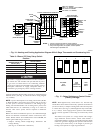
2. Non-Adaptive Heating Mode—Two-Stage Thermostat and
2-Stage Heating
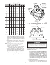
(See Fig. 16 for thermostat connections.)
NOTE: The low-heat-only switch SW-2 ON selects low-heat-
only operation mode in response to closing thermostat R-W/W1
circuit. When high-heat-only switch SW-1 is off, closing thermo-
stat R to W1-and-W2 circuits is required for high-gas-heat
operation. When high-heat-only switch SW-1 is on, it always
causes high-gas-heat operation when R-W/W1 circuit is closed,
regardless of setting of low-heat-only switch SW-2 and regardless
of whether R-W2 circuit is closed or open.
The start-up and shutdown functions and delays described in
item 1 above apply to 2-stage heating mode as well, except for
switching from low- to high-gas heat and vice versa.
a. When wall thermostat "calls for heat," R-W/W1 circuit
closes for low-gas heat or R to W1-and-W2 circuits close
for high-gas heat. The furnace control performs a self-
check, verifies low-heat and high-heat pressure switch
contacts LPS and HPS are open, and starts inducer motor
IDM in low speed or high speed as appropriate.
b. Switching from low- to high-gas heat—If thermostat
R-W/W1 circuit for low-gas heat is closed and R-W2
circuit for high-gas heat closes, control CPU switches
inducer motor IDM speed from low to high. The high-heat
pressure switch relay HPSR closes. When inducer motor
IDM provides sufficient pressure to close high-heat pres-
sure switch HPS, high-heat gas valve solenoid GV is
energized. Blower motor BLWM switches speed for high-
gas heat 5 sec after R-W2 circuit closes.
c. Switching from high- to low-gas heat—If thermostat R-W2
circuit for high-gas heat opens and R-W/W1 circuit for
low-gas heat remains closed, control CPU switches inducer
motor IDM speed from high to low. The high-heat pressure
switch relay HPSR opens to de-energize high-heat gas
valve solenoid GV. When inducer motor IDM reduces
pressure sufficiently, high-heat pressure switch HPS opens.
The low-heat gas valve solenoid GV remains energized as
long as low-heat pressure switch LPS remains closed.
Blower motor BLWM switches speed for low-gas heat 5
sec after R-W2 circuit opens.
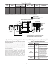
3. Cooling Mode
a. Single-Speed Cooling Outdoor Unit
(See Fig. 15 for thermostat connections.)
14