


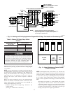
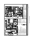
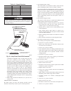
components in R-W/W1 circuit. Accurate amp draw read-
ings can be obtained at wires normally connected to
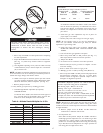
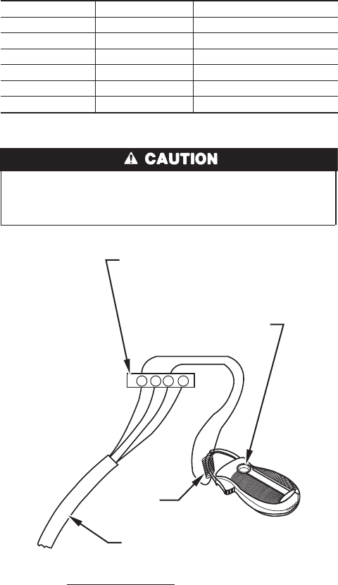
thermostat subbase terminals R and W/W1. Fig. 21 illus-
trates an easy method of obtaining actual amp draw. The
amp reading should be taken after blower motor has started
and furnace is operating in low heat. To operate furnace in
low heat, first move SW-2 to ON position, THEN connect
ammeter wires as shown in Fig. 21. The thermostat
anticipator should NOT be in this circuit while measuring
current. If thermostat has no subbase, thermostat MUST be
disconnected from R and W/W1 wires during current
measurement. Return SW-2 to final desired location after
completing reading. See thermostat manufacturer’s instruc-
tions for adjusting heat anticipator and for varying heating
cycle length.
b. When using an electronic thermostat, set cycle rate for 3
cycles per hr.
CHECK SAFETY CONTROLS
The flame sensor, gas valve, and pressure switches were all
checked in the Start-Up section as part of normal operation.
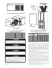
1. Check primary limit control.
This control shuts off combustion control system and ener-
gizes circulating-air blower motor if furnace overheats.
The preferred method of checking limit control is to gradually
block off return air after furnace has been operating for a
period of at least 5 minutes. As soon as limit has shut off
burners, return-air opening should be unblocked. By using this
method to check limit control, it can be established that the
limit is functioning properly and will operate if there is a
motor failure.
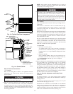
2. Check draft safeguard switch.
The purpose of this control is to permit safe shutdown of he
furnace during certain blocked vent conditions.
a. Disconnect power to furnace and remove vent connector
from furnace flue collar. Be sure to allow time for vent
connector pipe to cool down before removing.
b. Restore power to furnace and set room thermostat above
room temperature.
c. After normal start-up, allow furnace to operate for 2
minutes, then block flue outlet 100 percent. Furnace should
cycle off within 2 minutes.
d. Remove blockage and reconnect vent connector to furnace
flue collar.
e. Wait 5 minutes and then reset draft safeguard switch.
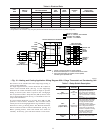
3. Check flow-sensing pressure switches.
This control proves operation of draft inducer blower.
a. Turn off 115-v power to furnace.
b. Remove gas control door and disconnect inducer motor
lead wires from wire harness.
c. Turn on 115-v power to furnace
d. Close thermostat switch as if making normal furnace start.
If hot surface ignitor does not glow within several minutes
and control flashes code 32, pressure switches are func-
tioning properly.
e. Turn off 115-v power to furnace.
f. Reconnect inducer motor wires, replace gas control door,
and turn on 115-v power to furnace.
4. Check auxiliary limits.
a. Turn off 115-v power to furnace.
b. Remove blower access door.
c. Disconnect red motor lead at blower speed selector. Mark
terminal for proper reconnection.
d. Replace blower access door.
e. Turn on 115-v power to furnace. Be sure room thermostat
is calling for low heat.
f. Allow furnace to operate until auxiliary limit activates, but
DO NOT operate furnace longer than 4 minutes.
g. If furnace operates for 4 minutes, check/replace limit
switch(es).
h. Turn off 115-v power to furnace.
i. Remove blower access door.
j. Reconnect red motor lead, reset switch, and replace door.
k. Turn on 115-v power to furnace.
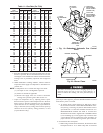
Table 12—Speed Selection
COLOR SPEED AS SHIPPED
White Common C
OM
Black High Cool
Yellow Med-High SPARE
Orange† Med SPARE or Capped
Blue Med-Low High-Gas-Heat
Red Low* Low-Gas-Heat
* Continuous fan speed.
† Available on 5-speed blowers only.
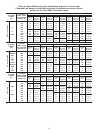
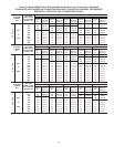
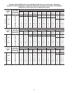
Recheck temperature rise. It must be within limits specified
on unit rating plate. Recommended operation is at midpointof
rise range or above.
Fig. 21—Amp Draw Check With Ammeter
A96316
R Y W G
10 TURNS
THERMOSTAT SUBBASE
TERMINALS WITH
THERMOSTAT REMOVED
(ANITICIPATOR, CLOCK, ETC.,
MUST BE OUT OF CIRCUIT.)
HOOK-AROUND
AMMETER
EXAMPLE:
5.0 AMPS ON AMMETER
10 TURNS AROUND JAWS
=
0.5 AMPS FOR THERMOSTAT
ANTICIPATOR SETTING
FROM UNIT 24-V
CONTROL TERMINALS
22