


(1.) The thermostat closes R to G-and-Y circuits. The
R-Y circuit starts outdoor unit, and R to G-and-Y
circuits start furnace blower motor BLWM on high-
cool speed.
(2.) The EAC terminals EAC-1 and EAC-2 are energized
with 115v when blower motor BLWM is operating.
(3.) When thermostat is satisfied, R to G-and-Y circuits
are opened. The outdoor unit stops, and furnace
blower motor BLWM continues operating on high-
cool speed for an additional 90 sec.
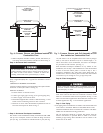
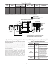
b. Two-Speed Cooling Outdoor Unit
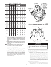
(See Fig. 16 for thermostat connections.)
(1.) The thermostat closes R to G-and-Y1 circuits for low
cooling or closes R to G-and-Y1-and-Y/Y2 circuits
for high cooling. The R-Y1 circuits start outdoor unit
on low-cooling speed, and R-G circuit starts furnace
blower motor BLWM on low-cooling speed (same
speed as for low-gas heat). The R to Y1-and-Y2
circuits start outdoor unit on high-cooling speed, and
R to G-and-Y2 circuits start furnace blower motor
BLWM on high-cooling speed.
NOTE: Y1 is not located on furnace control, but is found in
outdoor unit. The furnace control CPU controls blower motor
BLWM speed by sensing only G for low-cooling speed and Y/Y2
for high-cooling speed.
(2.) The EAC terminals EAC-1 and EAC-2 are energized
with 115v when blower motor BLWM is operating on
either cooling speed.
(3.) When thermostat is satisfied, R to G-and-Y1 or
R to G-and-Y1-and-Y/Y2 circuits open. The outdoor
unit stops, and furnace blower continues operating on
cooling speed for an additional 90 sec.
4. Continuous Blower Mode
a. When R to G circuit is closed by thermostat, blower motor
BLWM operates on low-gas-heat speed (identical to low-
cool speed). Terminals EAC-1 and EAC-2 are energized
with 115v as long as blower motor BLWM is energized.
b. During "call for heat," blower motor BLWM stops during
ignitor warm-up (17 sec), ignition (7 sec), and blower on
delay (45 sec), allowing furnace heat exchangers to heat up
quickly.
(1.) The blower motor BLWM reverts to continuous
blower speed after heating cycle is completed. In
high-gas-heat, furnace control CPU holds blower mo-
tor BLWM at high-gas-heat speed during selected
blower off delay period before reverting to continuous
blower speed.
(2.) When thermostat "calls for low cooling," blower
motor BLWM continues to operate on low-cool speed.
When thermostat is satisfied, blower motor BLWM
continues on continuous blower speed.
(3.) When thermostat "calls for high cooling," blower
motor BLWM operates on high-cool speed. When
thermostat is satisfied, blower motor BLWM operates
an additional 2 sec on high-cool speed before reverting
back to continuous blower speed.
(4.) When R to G circuit is opened, blower motor BLWM
continues operating for an additional 90 sec if no other
function requires blower motor BLWM operation.
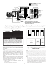
5. Heat Pump
NOTE: An accessory interface kit is required with single-speed
heat pumps. See interface kit Installation Instructions for single-
speed heat pump thermostat and interface connections. No inter-
face kit is needed for 2-speed heat pumps. See 2-speed heat pump
Installation Instructions for thermostat connections.
a. Single-Speed Heat Pump Cooling
(1.) The thermostat and interface kit close R to G-and-
Y/Y2 circuit to start furnace blower motor BLWM on
high-cooling speed. (Y/Y2 input to furnace control is
necessary to provide adequate cooling airflow.)
(2.) The EAC terminals EAC-1 and EAC-2 are energized
with 115v when blower motor BLWM is operating.
(3.) When thermostat is satisfied, furnace blower motor
BLWM continues operating on high-cooling speed for
an additional 90 sec.
b. Two-Speed Heat Pump Cooling
(1.) The thermostat R to G circuits start furnace blower
motor BLWM on low-cooling speed. Thermostat
R to G-and-Y/Y2 circuits start furnace blower motor
BLWM on high-cool speed.
NOTE: The furnace control CPU controls blower motor BLWM
speed by sensing only G (for low-cooling speed) and Y2 (for
high-cooling speed).
(2.) The EAC terminals EAC-1 and EAC-2 are energized
with 115v when blower motor BLWM is operating on
either cooling speed.
(3.) When thermostat is satisfied, furnace blower motor
BLWM continues operating on cooling speed for an
additional 90 sec.
c. Single-Speed Heat Pump Heating
(1.) The thermostat and accessory interface kit R to G-
and-Y/Y2 circuits start furnace blower motor BLWM
on heat pump high-heat speed (identical to high-cool
speed).
(2.) The EAC terminals EAC-1 and EAC-2 are energized
with 115v when blower motor BLWM is operating.
(3.) When thermostat is satisfied, furnace blower motor
BLWM continues operating on heat pump high-heat
speed for an additional 90 sec.
d. Two-Speed Heat Pump Heating
(1.) The thermostat closes R to G circuit for low heat and
starts furnace blower motor BLWM on heat pump
low-heat speed (identical to low-cooling speed). Clos-
ing R-Y/Y2 circuit to furnace provides blower motor
BLWM heat pump high-heat speed.
NOTE: The furnace control CPU controls blower motor BLWM
speed by sensing only G (for heat pump low-heat speed) and Y2
(for heat pump high-heat speed).
(2.) The EAC terminals EAC-1 and EAC-2 are energized
with 115v when blower motor BLWM is operating on
either heating speed.
(3.) When thermostat is satisfied, R to G or R to G-and-
Y2 circuits are opened. After opening R to G-and-Y2
circuit, the furnace blower motor BLWM continues
operating on heating speed for an additional 90 sec.
(4.) Opening R-Y2 circuit reduces blower motor BLWM
speed to heat pump low-heat speed.
6. Defrost
a. When furnace control R to W/W1-and-Y/Y2 circuits are
closed, furnace control CPU continues blower motor
15