


ELECTROSTATIC DISCHARGE (ESD) PRECAUTIONS
PROCEDURE
Electrostatic discharge can affect electronic components.
Take precautions during furnace installation and servicing to
protect the furnace electronic control. Precautions will pre-
vent electrostatic discharges from personnel and hand tools
which are held during the procedure. These precautions will
help to avoid exposing the control to electrostatic discharge
by putting the furnace, the control, and the person at the same
electrostatic potential.
1. Disconnect all power to the furnace. DO NOT TOUCH THE
CONTROL OR ANY WIRE CONNECTED TO THE CON-
TROL PRIOR TO DISCHARGING YOUR BODY’S ELEC-
TROSTATIC CHARGE TO GROUND.
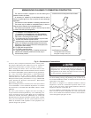
2. Firmly touch a clean, unpainted, metal surface of the furnace
chassis which is close to the control. Tools held in a person’s
hand during grounding will be satisfactorily discharged.
3. After touching the chassis you may proceed to service the
control or connecting wires as long as you do nothing that
recharges your body with static electricity (for example; DO
NOT move or shuffle your feet, DO NOT touch ungrounded
objects, etc.).
4. If you touch ungrounded objects (recharge your body with
static electricity), firmly touch furnace again before touching
control or wires.
5. Use this procedure for installed and uninstalled (ungrounded)
furnaces.
6. Before removing a new control from its container, discharge
your body’s electrostatic charge to ground to protect the
control from damage. If the control is to be installed in a
furnace, follow items 1 through 5 before bringing the control
or yourself into contact with the furnace. Put all used AND
new controls into containers before touching ungrounded
objects.
7. An ESD service kit (available from commercial sources) may
also be used to prevent ESD damage.
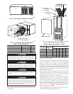
INTRODUCTION
The model 58TMA Series 111 Furnace is available in sizes 65,000
through 123,000 Btuh input capacities.
The design of the downflow/horizontal gas-fired furnace is
A.G.A./C.G.A. certified for natural and propane gases and for
installation on noncombustible flooring. The furnace is factory-
shipped for use with natural gas. The manufacturer’s accessory gas
conversion kit is required to convert furnace for use with propane
gas.
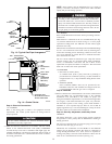
These furnaces SHALL NOT be installed directly on carpeting,
tile, or any other combustible material other than wood flooring. In
downflow installations, the manufacturer’s accessory floor base
must be used when installed on combustible materials and wood
flooring. Special base is not required when this furnace is installed
on manufacturer’s Coil Assembly Part No. CD5 or CK5, or when
Coil Box Part No. KCAKC is used. This furnace is for installation
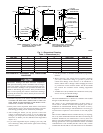
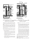
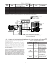
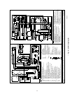
Fig. 1—Dimensional Drawing
A88324
4
3
⁄
16
″
2″
2
15
⁄
16
″
13
⁄
16
″
11
⁄
16
″
9
1
⁄
8
″
10
1
⁄
4
″
1
1
⁄
16
″
2
1
⁄
8
″
8
1
⁄
4
″
10
1
⁄
4
″
1
1
⁄
16
″
2
1
⁄
8
″
16
1
⁄
16
″
13
5
⁄
16
″
19″
11
⁄
16
″
13
⁄
16
″
11
⁄
16
″
20″
28
1
⁄
2
″
39
7
⁄
8
″
D
5
⁄
8
″ TYP
1
″ TYP
E
A
AIRFLOW
OUTLET
INLET
1
⁄
2
″ DIA
THERMOSTAT
WIRE ENTRY
7
⁄
8
″ DIA
ACCESSORY
7
⁄
8
″ DIA
ACCESSORY
DIMPLES TO DRILL HOLES
FOR HANGER BOLTS (4 PLACES)
IN HORIZONTAL POSITION
ADDITIONAL
7
⁄
8
″ DIA K.O. ARE
LOCATED IN THE TOP PLATE
AND BOTTOM PLATE
NOTE:
7
⁄
8
″ DIA HOLE
POWER ENTRY
1
1
⁄
2
″ DIA
R.H. GAS ENTRY
7
⁄
8
″ DIA
ACCESSORY
1
3
⁄
4
″ DIA HOLE
GAS ENTRY
VENT CONNECTION
Table 1—Dimensions (In.)
UNIT SIZE A D E VENT CONN SHIP. WT
065-08 14-3/16 12-9/16 12-11/16 4 141
065-12 14-3/16 12-9/16 12-11/16 4 145
085-12 17-1/2 15-7/8 16 4 154
085-16 17-1/2 15-7/8 16 4 154
105-16 17-1/2 15-7/8 16 4 171
105-20 21 19-3/8 19-1/2 4 181
125-20 24-1/2 22-7/8 23 5 192
2
→