


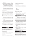
his furnace is equipped with 2 manual reset limit switches in
gas control area. The switches will open and shut off power
to gas valve if a flame rollout or an overheating condition
occurs in gas control area. DO NOT bypass switches. Correct
inadequate combustion air supply, component failure, re-
stricted flue gas passageway before resetting switches.
SEQUENCE OF OPERATION
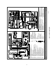
Using the schematic diagram follow sequence of operation through
different modes. (See Fig. 18.) Read and follow wiring diagram
very carefully.
NOTE: If power interruption occurs during "call for heat" (W/W1
or W/W1-and-W2), control starts 90-sec blower only on period 2
sec after power is restored if thermostat is still calling for gas
heating. The red LED flashes code 12 during 90-sec period, after
which LED will be on continuously as long as no faults are
detected. After 90-sec period, furnace responds to thermostat
normally.
Blower door must be installed for power to be conducted through
blower door interlock switch ILK to furnace control CPU, trans-
former TRAN, inducer motor IDM, blower motor BLWM, hot
surface ignitor HSI, and gas valve GV.
1. Adaptive Heating Mode—Single-Stage Thermostat and
2-Stage Heating
(See Fig. 16 for thermostat connections.)
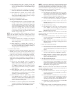
NOTE: With high-heat-only switch SW-1 off, low-heat-only
switch SW-2 selects either low-heat-only operation mode when on
(see item 2. below), or adaptive heating mode when off in response
to "call for heat." (See Fig. 17.) When high-heat-only switch SW-1
is on, it always causes high-gas-heat operation when R-W/W1
circuit is closed, regardless of the setting of low-heat-only switch
SW-2.
This furnace can operate as a 2-stage furnace with a single-
stage thermostat because furnace control CPU includes a
programmed adaptive sequence of controlled operation which
selects low-gas-heat or high-gas-heat operation. This selection
is based upon stored history of the length of previous gas
heating on/off periods of single-stage thermostat.
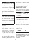
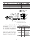
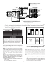
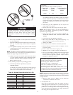
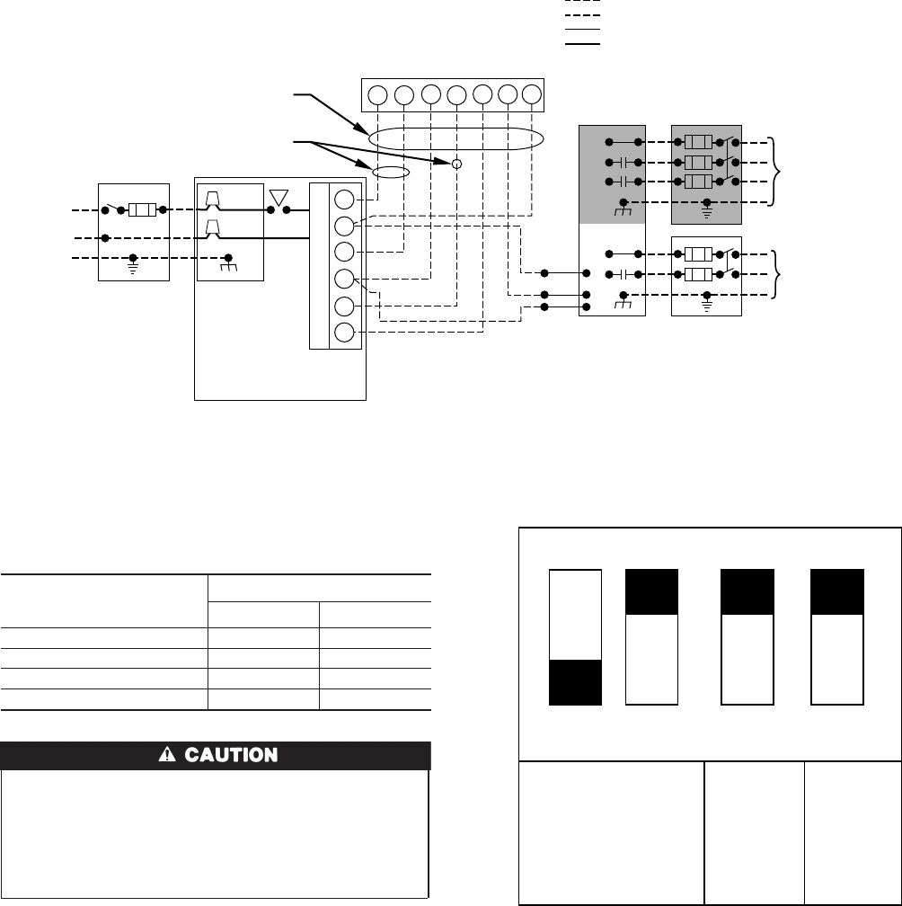
→ Fig. 16—Heating and Cooling Application Diagram With 2-Stage Thermostat and Condensing Unit
A97444
115-V FUSED
DISCONNECT
SWITCH
(WHEN REQUIRED)
JUNCTION
BOX
CONTROL
BOX
24-V
TERMINAL
BLOCK
THREE-WIRE
HEATING-
ONLY
SEVEN
WIRE
2-STAGE THERMOSTAT TERMINALS
FIELD-SUPPLIED
FUSED DISCONNECT
2-SPEED
CONDENSING
UNIT
FURNACE
G
R
W2 Y2 G Y1
C
GND
GND
FIELD 24-V WIRING
FIELD 115-, 208/230-, 460-V WIRING
FACTORY 24-V WIRING
FACTORY 115-V WIRING
208/230- OR
460-V
THREE
PHASE
208/230-V
SINGLE
PHASE
Y2
Y1
C
WHT
BLK
WHT
BLK
W1 R
W2
COM
W/W1
Y/Y2
NOTES: 1. Connect Y-terminal as shown for proper operation.
2. Some thermostats require a "C" terminal connection as shown.
3. If any of the original wire, as supplied, must be replaced,
use same type or equivalent wire.
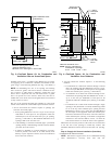
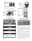
Table 8—Blower Off Delay Setup Switch
Position
DESIRED HEATING
MODE BLOWER OFF
DELAY (SEC)
SETUP SWITCH
SW-3 SW-4
90 OFF OFF
135 OFF ON
180 ON OFF
225 ON ON
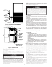
→ Fig. 17—Setup Switches on Control Center
(Factory Settings)
A96402
BLOWER-
OFF
DELAY
LOW
HEAT
(ADAPTIVE
ALGORITHM)
HIGH
HEAT
ONLY
43 2
OFF
ON
1
12