


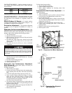
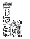


56
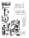
Fig. 45 — Typical Component Arrangement — 48PG28
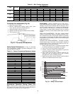
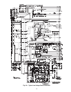
THERMOSTAT/IGC MARKINGS
BM — Blower Motor
C—Common
CM — Inducer Motor
CS — Centrifugal Switch
G—Fan
IFO — Indoor Fan On
L1 — Line 1
R—Thermostat Power
RT — Power Supply
SS — Speed Sensor
W—ThermostatHeat
W1 — 1stStage of Heating
W2 — 2ndStage of Heating
X—Alarm Output
Y1 — 1st Stage of Cooling
Y2 — 2nd Stage of Cooling
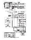
LEGEND FOR FIG. 42-45
---A — Circuit A
AUX — Auxiliary Contact
AL — Ambient Limit
---B — Circuit B
C—Compressor Contactor
CAP — Capacitor
CB — Compressor Circuit Breaker
CCH — Crankcase Heater
CLO — Compressor Lockout
COMP — Compressor
CT BRK— Circuit Breaker
CR — Control Relay
DU — Dummy Terminal
ECB — Economizer Control Board
FCS — Fan Cycling Switch
FIOP — Factory-Installed Option
FPT — Freeze ProtectionThermostat
FS — Flame Sensor
FU — Fuse
GND — Ground
GV — Gas Valve
HACR — Heating, Air Conditioning,
and Refrigeration
HERM — Hermetic
HPS — High-Pressure Switch
I—Ignitor
IAQ — Indoor Air Quality
IDM — Induced-Draft Motor
IDR — Induced Draft Relay
IFC — Indoor-Fan Contactor
IFCB — Indoor Fan CircuitBreaker
IFM — Indoor-Fan Motor
IGC — Integrated GasController
LOR — Lockout Relay
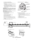
NOTES:
1. Factory wiring is in accordance with the National Electrical Codes. Any
field modifications or additions must be in compliance with all applicable
codes.
2. Use75° C min wire forfield power supply. Use copperwires forall units.
3. All circuitbreakers “Must Trip Amps” are equal to or less than 156% RLA.
4. Compressor and fan motors are thermally protected. Three-phase motors
protected against primary single-phase conditions.
5. The CLO locksout the compressorto prevent short cycling on compressor
overload andsafety devices. Before replacingCLO,check these devices.
LPS — Low-Pressure Switch
LS — Limit Switch
OAS — Outdoor-Air Sensor
OFC — Outdoor-Fan Contactor
OFM — Outdoor-FanMotor
PEC — Power Exhaust Contactor
PEM — Power Exhaust Motor
PL — Plug
PLP — Phase Loss Protection
QC — Quick Connect
QT — Quadruple Terminal
RAS — Return Air Sensor
RS — Rollout Switch
SAT — Supply-Air Temperature
TB — Ter m i n a l B l o c k
TRAN — Transformer
TXV — Thermostatic Expansion Valve
W/AT — With Auxiliary Trip
Te r m i n al B l ock
Terminal (Unmarked)
Te r m i n al ( Marked)
Factory Wiring
Field Wiring
To Indicate Common Potential
Only. Not to Represent Wiring.
To Indicate FIOP or Accessory