


47
5. Thoroughly apply Totaline® environmentally sound coil
cleaner solution to all coil surfaces including finned area,
tube sheets and coil headers.
6. Hold garden sprayer nozzle close to finned areas and ap-
ply cleaner with a vertical, up-and-down motion. Avoid
spraying in horizontal pattern to minimize potential for
fin damage.
7. Ensure cleaner thoroughly penetrates deep into finned
areas.
8. Interior and exterior finned areas must be thoroughly
cleaned.
9. Finned surfaces should remain wet with cleaning solution
for 10 minutes.
10. Ensure surfaces are not allowed to dry before rinsing. Re-
applying cleaner as needed to ensure 10-minute satura-
tion is achieved.
11. Thoroughly rinse all surfaces with low velocity clean wa-
ter using downward rinsing motion of water spray nozzle.
Protect fins from damage from the spray nozzle.
CONDENSATE DRAIN — Check and clean each year at the
start of the cooling season. In winter, keep drains and traps dry.
An access panel is located above the condensate connection to
allow easy clean out of the condensate pan. The first time the
panel is removed, the insulation behind the access panel will
need to be cut away. Carefully cut the insulation with a knife or
blade on three sides so the insulation can be folded out of the
way during cleaning. Be careful not to damage components be-
hind the insulation while cutting. Once cleaning is completed,
fold the insulation back into place and secure the access panel
in the original position.
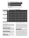
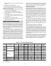
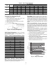
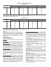
FILTERS — Clean or replace at start of each heating and cool-
ing season, or more often if operating conditions require. Refer
to Table 1 for type and size.
OUTDOOR-AIR INLET SCREENS — Clean screens with
steam or hot water and a mild detergent. Do not use throwaway
filters in place of screens. See Table 2 for quantity and size.
MAIN BURNER — At the beginning of each heating season,
inspect for deterioration or blockage due to corrosion or other
causes. Observe the main burner flames. Refer to Main Burn-
ers section on page 51.
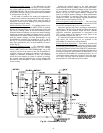
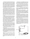
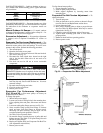
FLUE GAS PASSAGEWAYS — The flue collector box and
heat exchanger cells may be inspected by removing heat
section access panel (Fig. 4), flue box cover, and main burner
assembly (Fig. 31). Refer to Main Burners section on page 51
for burner removal sequence. If cleaning is required, clean
tubes with a wire brush.
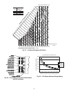
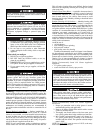
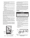
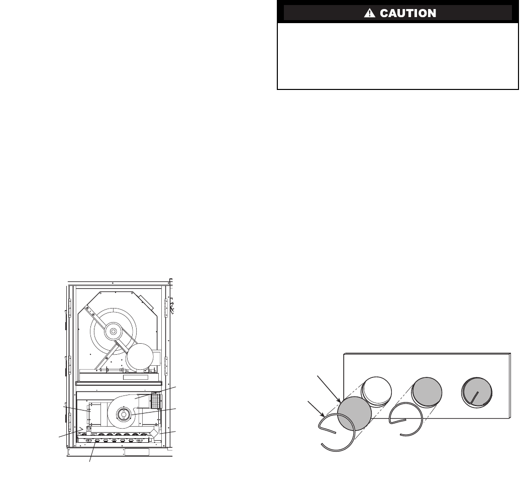
Use caution with ceramic heat exchanger baffles. When in-
stalling retaining clip, be sure the center leg of the clip extends
inward toward baffle. See Fig. 32.
COMBUSTION-AIR BLOWER — Clean periodically to as-
sure proper airflow and heating efficiency. Inspect blower
wheel every fall and periodically during heating season. For the
first heating season, inspect blower wheel bi-monthly to deter-
mine proper cleaning frequency.
To inspect blower wheel, remove heat section panel. Using
an inspection mirror and flashlight, look into the flue exhaust
duct to inspect the wheel. If cleaning is required, remove motor
and wheel assembly by removing the screws holding the flue
box cover to the flue box. See Fig. 31. Remove the screws hold-
ing the inducer housing to the inlet plate. The wheel can then be
removed from the motor shaft and cleaned with a detergent or
solvent. Replace the wheel onto the motor shaft in the correct
position and reassemble the flue cover onto the flue box.
Lubrication
COMPRESSORS — Each compressor is charged with the
correct amount of oil at the factory.
Polyolester (POE) compressor lubricants are known to
cause long term damage to some synthetic roofing materials.
Exposure, even if immediately cleaned up, may cause roofing
materials to become brittle (leading to cracking) within a
year. When performing any service which may risk exposure of
compressor oil to the roof, take appropriate precautions to
protect roofing. Procedures which risk oil leakage include com-
pressor replacement, repairing refrigerant leaks, and replacing
refrigerant components. To prepare rooftop:
1. Cover extended roof work area with an impermeable
plastic dropcloth or tarp. Make sure a 10 x 10 area around
the work area is covered.
2. Cover area in front of the unit service panel with a terry
cloth shop towel to absorb lubricant spills and prevent
run-offs. Towel will also protect dropcloth from tears
caused by tools or components.
3. Place terrycloth shop towel inside the unit directly under
components to be serviced to prevent spills through the
bottom of the unit.
4. Perform the required service.
5. Remove and dispose of any oil contaminated material per
local codes.
The compressor is in a Puron® refrigerant system and uses
a polyolester (POE) oil. This oil is extremely hygroscopic,
meaning it absorbs water readily. POE oils can absorb
15 times as much water as other oils designed for HCFC
and CFC refrigerants. Avoid exposure of the oil to the
atmosphere. Damage to components could result.
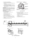
CERAMIC
BAFFLE
CLIP
NOTE: One baffle and clip will be in each upper tube of the heat
exchanger.
Fig. 32 — Removing Heat Exchanger Ceramic
Baffles and Clips
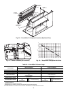
HEAT
EXCHANGER
SECTION
IGC BOARD
(HIDDEN)
COMBUSTION
FAN HOUSING
MAIN BURNER
SECTION
INDUCED
DRAFT
MOTOR
MAIN GAS
VALVE
Fig. 31 — Typical Gas Heating Section
IGC — Integrated Gas
Controller