


51
4. Set main gas valve to ON position.
5. Set thermostat at setting to call for heat.
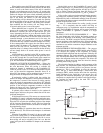
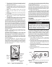
6. Remove screw cap covering regulator adjustment screw
(see Fig. 40).
7. Turn adjustment screw clockwise to increase pressure or
counterclockwise to decrease pressure.
8. Once desired pressure is established, set unit setting
for no call for heat, turn off main gas valve, remove
pressure-measuring device, and replace
1
/
8
-in. pipe
plug and screw cap.
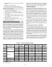
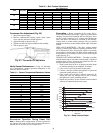
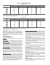
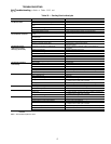
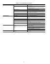
High Altitude — For high altitude applications greater
than 2000 ft the heat input rate should be reduced. The higher
the altitude is above sea level, the less oxygen is in the air. See
Table 32 for orifice sizing. A high altitude kit is available to
convert unit for altitudes up to 7,000 ft.
Main Burners — For all applications, main burners are
factory set and should require no adjustment.
MAIN BURNER REMOVAL
1. Shut off (field-supplied) manual main gas valve.
2. Shut off power to unit.
3. Remove gas section access panel.
4. Disconnect gas piping from gas valve inlet.
5. Remove wires from gas valve.
6. Remove wires from rollout switch.
7. Remove sensor wire and ignitor cable from IGC board.
8. Remove 2 screws securing manifold bracket to basepan.
9. Remove 2 screws that hold the burner assembly to vesti-
bule plate.
10. Lift burner/manifold assembly out of unit.
CLEANING AND ADJUSTMENT
1. Remove burner rack from unit as described in Main
Burner Removal section above.
2. Inspect burners, and if dirty, remove burners from rack.
3. Using a soft brush, clean burners and crossover port as
required.
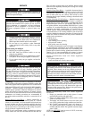
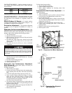
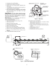
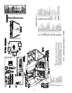
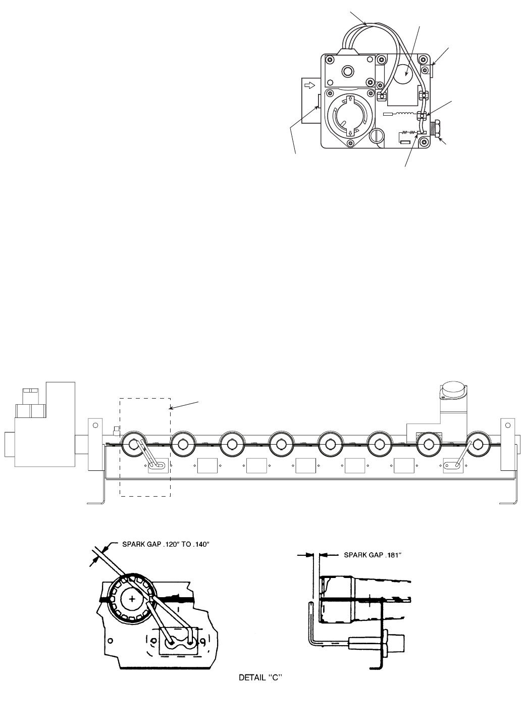
4. Adjust spark gap. See Fig. 41.
5. Reinstall burners on rack.
6. Reinstall burner rack as described above.
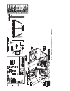
OFF
ON
W-1
W-2
D-1
D-2
C1
C2
PILOT
ADJ.
INLET PRESSURE TAP
(PLUGGED)
1/8 - 27 N.P.T. THDS.
2 LEADS, #18 WIRE 1/32 INSULATION,
600V. MAX., 105°C
REGULATOR
ADJUSTMENT SCREW
(REMOVE COVER)
OUTLET PRESSURE
TAP(PLUGGED)
1/8-27 N.P.T. THDS.
PILOT CONNECTION
FOR 1/4” O.D. TUBING
(PLUGGED)
RECEPTACLEAND
TAB COMBINATION
TERMINAL
RECEPTACLETERMINAL
Fig. 40 — Gas Valve
SEE DETAIL“C”
Fig. 41 — Spark Gap Adjustment