


16
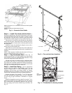
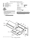
Step 11 — Position Optional Power Exhaust or
Barometric Relief Damper Hood —
The optional
power exhaust or barometric relief dampers are shipped
assembled and tilted back into the unit for shipping. Brackets
and extra screws are shipped in shrink wrap around the
dampers.
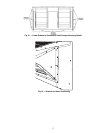
1. Remove 9 screws holding each damper assembly in
place. See Fig. 21. Each damper assembly is secured with
3 screws on each side and 3 screws along the bottom.
Save screws.
2. Pivot the damper assembly outward until top edge of the
damper assembly rests against the inside wall of unit.
3. Secure each damper assembly to unit with 6 screws
across top (3 screws provided) and bottom (3 screws
from Step 1) of damper.
4. With screws saved from Step 1, install brackets on each
side of damper assembly. See Fig. 22.
5. Remove tape from damper blades.
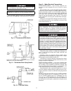
Step 12 — Non-Fused Disconnect — The handle
for the factory-installed non-fused disconnect is shipped inside
the unit to prevent the handle from damage during shipping.
Follow these steps to complete installation of the handle.
1. Open the control box access door.
2. Remove the small cover plate located on the unit corner
post near the control section.
3. Remove the inner control box cover. The handle and shaft
are located in a plastic bag at the bottom of the control
box.
4. Insert the square shaft into the disconnect with the pins
vertical. On the 100-amp disconnect, the shaft is keyed
into the disconnect and can only be installed one way
(with the pins vertical).
5. Insert the handle through the corner post and onto the
shaft with the handle positioned so that “OFF” is on top.
6. Rotate the handle to the “ON” position to lock the pins
into the handle.
7. From the inside of the corner post, attach the handle
mounting screws to the handle. Slide the shaft fully into
the handle and tighten the set screw(s) on the disconnect
to lock the shaft. Tighten the screws that attach the handle
to the corner post.
8. Rotate the handle back to the “OFF” position.
9. Replace all panels and doors. Power can now be turned
back on to the unit.
Step 13 — Install All Accessories — After all of
the factory-installed options have been adjusted, install all
field-installed accessories. Refer to the accessory installation
instructions included with each accessory. Consult the Carrier
Price Pages for accessory package numbers for particular
applications.
Be careful when tilting blower assembly. Hoods and blow-
ers are heavy and can cause injury if dropped.
BESUREPOWERISSHUTOFFTOTHEUNITFROM
THE BUILDING POWER SUPPLY. Electrical shock
could cause personal injury.
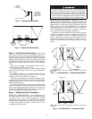
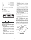
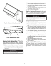
MOVEABLE DAMPER
AIR FILTER POSITION
LOCKING SCREW
MOVEABLE DAMPER
Fig. 19 — Outdoor-Air Hood Assembled
Fig. 20 — Manual Damper Details