


18
PRE-START-UP
Proceed as follows to inspect and prepare the unit for initial
start-up:
1. Remove all access panels.
2. Read and follow instructions on all WARNING, CAU-
TION, and INFORMATION labels attached to, or
shipped with, the unit.
3. Make the following inspections:
a. Inspect for shipping and handling damages such as
broken lines, loose parts, or disconnected wires, etc.
b. Inspect for oil at all refrigerant tubing connections
and on unit base. Detecting oil generally indicates a
refrigerant leak. Leak-test all refrigerant tubing con-
nections using an electronic leak detector, halide
torch, or liquid-soap solution.
c. Inspect all field-wiring and factory-wiring connec-
tions. Be sure that connections are completed and
tight.
d. Inspect coil fins. If damaged during shipping and
handling, carefully straighten the fins with a fin
comb.
4. Verify the following conditions:
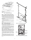
a. Make sure that condenser fan blade is correctly
positioned in the fan orifice. See Condenser-Fan
Adjustment section on page 49 for more details.
b. Make sure that air filter(s) is in place.
c. Make sure that condensate drain trap is filled with
water to ensure proper drainage.
d. Make sure that all tools and miscellaneous loose parts
have been removed.
START-UP
Use the following information and Start-Up Checklist on
page CL-1 to check out unit PRIOR to start-up.
Unit Preparation — Check that unit has been installed in
accordance with these installation instructions and all applica-
ble codes.
Compressor Mounting — Compressors are internally
spring mounted. Do not loosen or remove compressor hold-
down bolts.
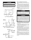
Refrigerant Service Ports — Each independent re-
frigerant system has a total of 3 Schrader-type service gage
ports per circuit. One port is located on the suction line, one on
the compressor discharge line, and one on the liquid line. Be
sure that caps on the ports are tight.
Crankcase Heater(s) — Crankcase heaters are ener-
gized as long as there is power to the unit and the compressor is
not operating.
Compressor Rotation — On 3-phase units, it is impor-
tant to be certain the scroll compressor is rotating in the proper
direction. To determine whether or not compressor is rotating
in the proper direction:
1. Connect service gages to suction and discharge pressure
fittings.
2. Energize the compressor.
3. The suction pressure should drop and the discharge pres-
sure should rise, as is normal on any start-up.
If the suction pressure does not drop and the discharge pres-
sure does not rise to normal levels:
1. Note that the evaporator fan is probably also rotating in
the wrong direction.
2. Turn off power to the unit and install lockout tag.
3. Reverse any two of the unit power leads.
4. Turn on power to the unit.
The suction and discharge pressure levels should now move
to their normal start-up levels.
NOTE: When the compressor is rotating in the wrong direc-
tion, the unit makes an elevated level of noise and does not
provide heating or cooling.
Internal Wiring — Check all electrical connections in
unit control boxes; tighten as required.
Subcooler Heat Exchanger (SHX) — The subcool-
er heat exchanger adds approximately 10 to 15° F of sub-
cooling to the system. Check all valves and TXV (thermostatic
expansion valve).
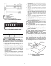
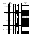
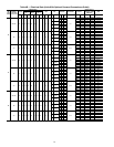
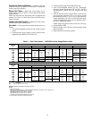
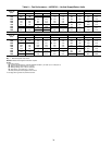
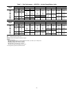
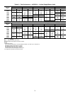
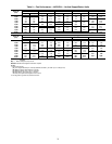
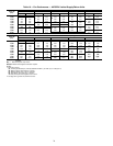
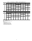
Evaporator Fan — Fan belt and variable pulleys are
factory-installed. See Tables 5-23 for fan performance data. Be
sure that fans rotate in the proper direction. See Table 24 for air
quantity limits. See Table 25 for evaporator fan motor specifi-
cations. See Table 26 for accessory/FIOP static pressure. See
Table 27 for fan rpm at various motor pulley settings. To alter
fan performance, see Evaporator Fan Performance Adjustment
sectiononpage48.
Failure to observe the following warnings could result in
serious personal injury.
1. Follow recognized safety practices and wear protective
goggles when checking or the servicing refrigerant
system.
2. Do not operate the compressor or provide any electric
power to the unit unless the compressor terminal cover
is in place and secured.
3. Do not remove the compressor terminal cover until all
electrical sources are disconnected.
4. Relieve all pressure from the system before touching or
disturbing anything inside the compressor terminal box
if refrigerant leak is suspected around the compressor
terminals.
5. Never attempt to repair a soldered connection while the
refrigerant system is under pressure.
6. Do not use torch to remove any component. The sys-
tem contains oil and refrigerant under pressure. To
remove a component, wear protective goggles and pro-
ceed as follows:
a. Shut off gas and then electrical power to the unit.
Install lockout tag.
b. Relieve all pressure from the system using both
high-pressure and low-pressure ports.
c. Cut the component connection tubing with a tubing
cutter, and remove the component from the unit.
d. Carefully unsweat the remaining tubing stubs when
necessary. Oil can ignite when exposed to torch
flame.
IMPORTANT: Unit power must be on for 24 hours prior
to start-up. Otherwise, damage to compressor may
result.
Compressor damage will occur if rotation is not immedi-
ately corrected.