


41
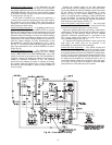
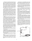
Differential Dry Bulb Control
— For differential dry bulb
control the standard outdoor dry bulb sensor is used in conjunc-
tion with an additional accessory dry bulb sensor (part number
CRTEMPSN002A00). The accessory sensor must be mounted
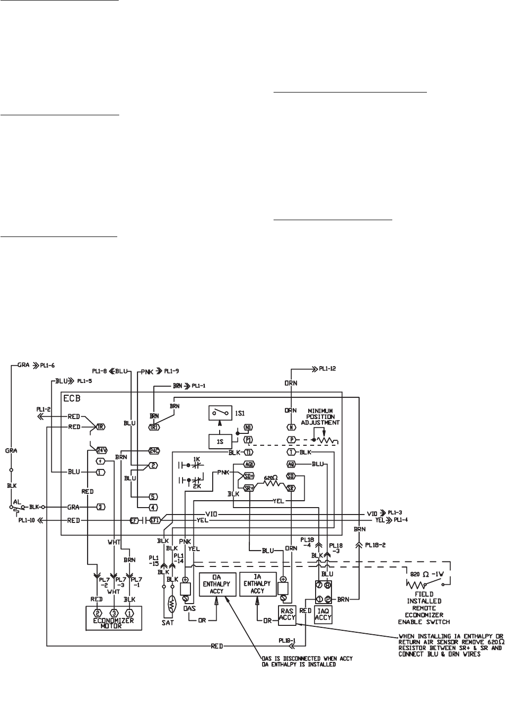
in the return airstream. Wiring is provided in the EconoMi$er
IV wiring harness. See Fig. 26.
In this mode of operation, the outdoor-air temperature is
compared to the return-air temperature and the lower tempera-
ture airstream is used for cooling. When using this mode of
changeover control, turn the enthalpy set point potentiometer
fully clockwise to the D setting.
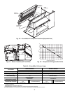
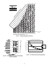
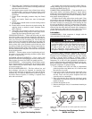
Outdoor Enthalpy Changeover
— For enthalpy control, acces-
sory enthalpy sensor (part number HH57AC078) is required.
Replace the standard outdoor dry bulb temperature sensor with
the accessory enthalpy sensor in the same mounting location.
When the outdoor air enthalpy rises above the outdoor enthalpy
changeover set point, the outdoor-air damper moves to its mini-
mum position. The outdoor enthalpy changeover set point is set
with the outdoor enthalpy set point potentiometer on the
EconoMi$er IV controller. The set points are A, B, C, and D.
See Fig. 27. The factory-installed 620-ohm jumper must be in
place across terminals S
R
and + on the EconoMi$er IV control-
ler. See Fig. 26.
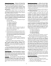
Differential Enthalpy Control
— For differential enthalpy
control, the EconoMi$er IV controller uses two enthalpy
sensors (HH57AC078 and CRENTDIF004A00), one in the
outside air and one in the return air duct. The EconoMi$er IV
controller compares the outdoor air enthalpy to the return air
enthalpy to determine EconoMi$er IV use. The controller
selects the lower enthalpy air (return or outdoor) for cooling.
For example, when the outdoor air has a lower enthalpy than
the return air, the EconoMi$er IV opens to bring in outdoor air
for free cooling.
Replace the standard outside air dry bulb temperature
sensor with the accessory enthalpy sensor in the same mount-
ing location. Mount the return air enthalpy sensor in the return
air duct. Wiring is provided in the EconoMi$er IV wiring
harness. See Fig. 26. The outdoor enthalpy changeover set
point is set with the outdoor enthalpy set point potentiometer
on the EconoMi$er IV controller. When using this mode of
changeover control, turn the enthalpy setpoint potentiometer
fully clockwise to the D setting. See Fig. 28.
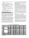
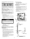
Indoor Air Quality (IAQ) Sensor Input
— The IAQ input
can be used for demand control ventilation control based on the
level of CO
2
measured in the space or return air duct.
Mount the optional IAQ sensor according to manufacturer
specifications. The IAQ sensor should be wired to the AQ and
AQ1 terminals of the controller. Adjust the DCV (demand
controlled ventilation) potentiometers to correspond to the
DCV voltage output of the indoor air quality sensor at the
user-determined set point. See Fig. 29.
If a separate field-supplied transformer is used to power the
IAQ sensor, the sensor must not be grounded or the
EconoMi$er IV control board will be damaged.
Exhaust Set Point Adjustment
— The exhaust set point will
determine when the exhaust fan runs based on damper position
(if accessory power exhaust is installed). The set point is modi-
fied with the Exhaust Fan Set Point (EXH SET) potentiometer.
See Fig. 28. The set point represents the damper position above
which the exhaust fans will be turned on. When there is a call
for exhaust, the EconoMi$er IV controller provides a 45 ± 15
second delay before exhaust fan activation to allow the damp-
ers to open. This delay allows the damper to reach the appro-
priate position to avoid unnecessary fan overload.
Fig. 26 — EconoMi$er IV Wiring