


39
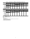
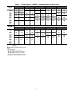
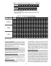
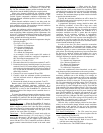
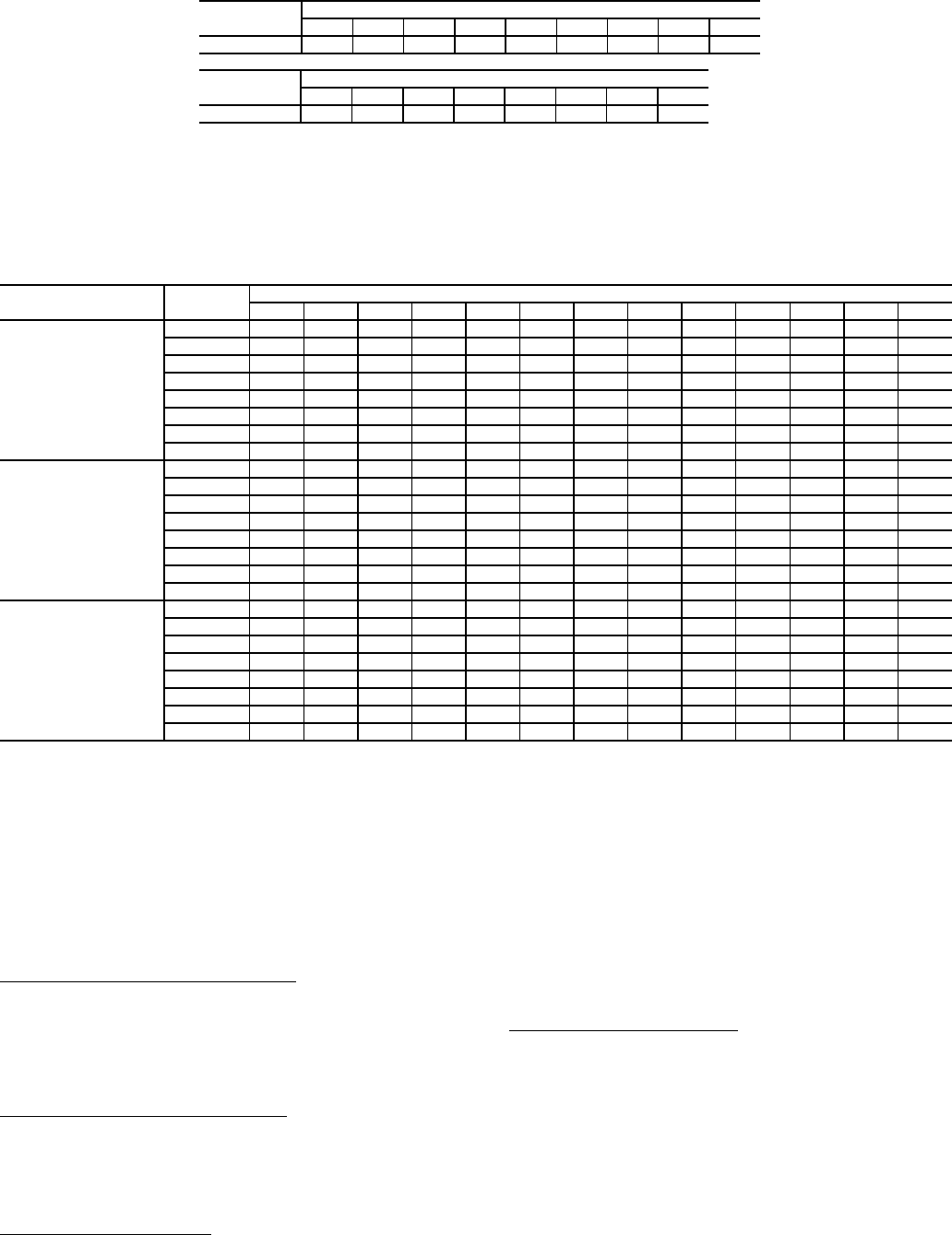
Table 26 — Accessory/FIOP Static Pressure (in. wg)* — 48PG20-28
LEGEND
*The static pressure must be added to the external static pressure. The sum and the evaporator
entering-air cfm should then be used in conjunction with the Fan Performance tables to deter-
mine blower rpm and watts.
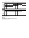
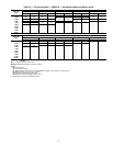
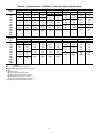
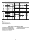
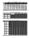
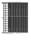
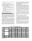
Table 27 — Fan Rpm at Motor Pulley Settings*
LEGEND *Approximate fan rpm shown.
NOTE: Factory pulley speed setting is at 3 turns open.
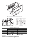
Optional EconoMi$er IV — See Fig. 23 for EconoMi$er
IV component locations. The optional EconoMi$er IV comes
from the factory fully wired and assembled. No field wiring or
assembly is required for standard outdoor dry bulb changeover
operation. Field wiring of accessory sensors is required for
different operational modes.
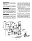
ECONOMI$ER IV STANDARD SENSORS
Outdoor Air Temperature (OAT) Sensor
— The outdoor air
temperature sensor is a 10 to 20 mA device used to measure the
outdoor-air temperature. The outdoor-air temperature is used to
determine when the EconoMi$er IV can be used for free
cooling. The sensor is factory-installed on the EconoMi$er IV
in the outdoor airstream. See Fig. 24. The operating range of
temperature measurement is 40 to 100 F.
Mixed-Air Temperature (MAT) Sensor
— The mixed-air
temperature sensor is a 3 K thermistor located at the outlet of
the indoor fan. See Fig. 24. This sensor is factory installed. The
operating range of temperature measurement is 0° to 158 F.
The temperature sensor is a short probe with blue wires
running to it.
Outdoor Air Lockout Sensor
— The Economi$er IV is
equipped with an ambient temperature lockout switch located
in the outdoor airstream which is used to lock out the compres-
sors below a 42 F ambient temperature.
ECONOMI$ER IV CONTROLLER WIRING AND OPER-
ATIONAL MODES — Determine the EconoMi$er IV control
mode before set up of the control. Some modes of operation may
require different sensors. Refer to Table 28. The EconoMi$er IV
is supplied from the factory with a mixed-air temperature
sensor and an outdoor air temperature sensor. This allows for
operation of the EconoMi$er IV with outdoor air dry bulb
changeover control. Additional accessories can be added to
allow for different types of changeover control and operation
of the EconoMi$er IV and unit.
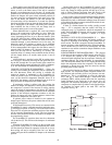
Outdoor Dry Bulb Changeover
— The standard controller is
shipped from the factory configured for outdoor dry bulb
changeover control. The outdoor air and mixed-air temperature
sensors are included as standard. For this control mode, the out-
door temperature is compared to an adjustable set point selected
on the control. If the outdoor-air temperature is above the set
point, the EconoMi$er IV will adjust the outdoor-air dampers to
minimum position. If the outdoor-air temperature is below the
set point, the position of the outdoor-air dampers will be con-
trolled to provided free cooling using outdoor air. When in this
mode, the LED next to the free cooling set point potentiometer
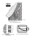
will be on. The changeover temperature set point is controlled
by the free cooling set point potentiometer located on the con-
trol. The scale on the potentiometer is A, B, C, and D. See
Fig. 25 for the corresponding temperature changeover values.
COMPONENT
CFM
4,000 4,500 5,000 5,500 6,000 6,500 7,000 7,500 8,000
Economizer 0.02 0.03 0.04 0.05 0.06 0.07 0.08 0.09 0.10
COMPONENT
CFM
8,500 9,000 9,500 10,000 10,500 11,000 11,500 12,000
Economizer 0.11 0.12 0.13 0.15 0.16 0.17 0.19 0.20
FIOP — Factory-Installed Option
UNIT
48PG
DRIVE
MOTOR PULLEY TURNS OPEN
0
1
/
2
11
1
/
2
22
1
/
2
33
1
/
2
44
1
/
2
55
1
/
2
6
20 and 24
(230 and 460 volt)
Low 685 706 727 749 770 791 812 833 854 876 897 918 939
Mid-Low 949 970 992 1013 1035 1056 1078 1099 1120 1142 1163 1185 1206
Mid-High 941 961 980 1000 1019 1039 1059 1078 1098 1117 1137 1156 1176
High 1014 1038 1061 1085 1108 1132 1156 1179 1203 1226 1250 1273 1297
Low n/a n/a n/a n/a n/a n/a n/a n/a n/a n/a n/a n/a n/a
Mid-Low 896 924 951 979 1006 1034 1062 1089 1117 1144 1172 1199 1227
Mid-High 1113 1138 1163 1188 1213 1238 1264 1289 1314 1339 1364 1389 1414
High 1096 1116 1137 1157 1177 1197 1218 1238 1258 1278 1299 1319 1339
20 and 24
(575 volt)
Low 751 768 785 802 819 836 853 869 886 903 920 937 954
Mid-Low 949 970 992 1013 1035 1056 1078 1099 1120 1142 1163 1185 1206
Mid-High 941 961 980 1000 1019 1039 1059 1078 1098 1117 1137 1156 1176
High 1014 1038 1061 1085 1108 1132 1156 1179 1203 1226 1250 1273 1297
Low n/a n/a n/a n/a n/a n/a n/a n/a n/a n/a n/a n/a n/a
Mid-Low 873 893 912 932 951 971 991 1010 1030 1049 1069 1088 1108
Mid-High 1113 1138 1163 1188 1213 1238 1264 1289 1314 1339 1364 1389 1414
High 1096 1116 1137 1157 1177 1197 1218 1238 1258 1278 1299 1319 1339
28
(all voltages)
Low 687 703 718 734 749 765 780 796 811 827 842 858 873
Mid-Low 805 822 839 856 872 889 906 923 940 957 973 990 1007
Mid-High 941 961 980 1000 1019 1039 1059 1078 1098 1117 1137 1156 1176
High 1014 1038 1061 1085 1108 1132 1156 1179 1203 1226 1250 1273 1297
Low 687 703 718 734 749 765 780 796 811 827 842 858 873
Mid-Low 805 822 839 856 872 889 906 923 940 957 973 990 1007
Mid-High 941 961 980 1000 1019 1039 1059 1078 1098 1117 1137 1156 1176
High 1014 1038 1061 1085 1108 1132 1156 1179 1203 1226 1250 1273 1297
n/a — not available