


12
Set heat anticipator settings as follows:
Settings may be changed slightly to provide a greater degree
of comfort for a particular installation.
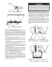
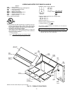
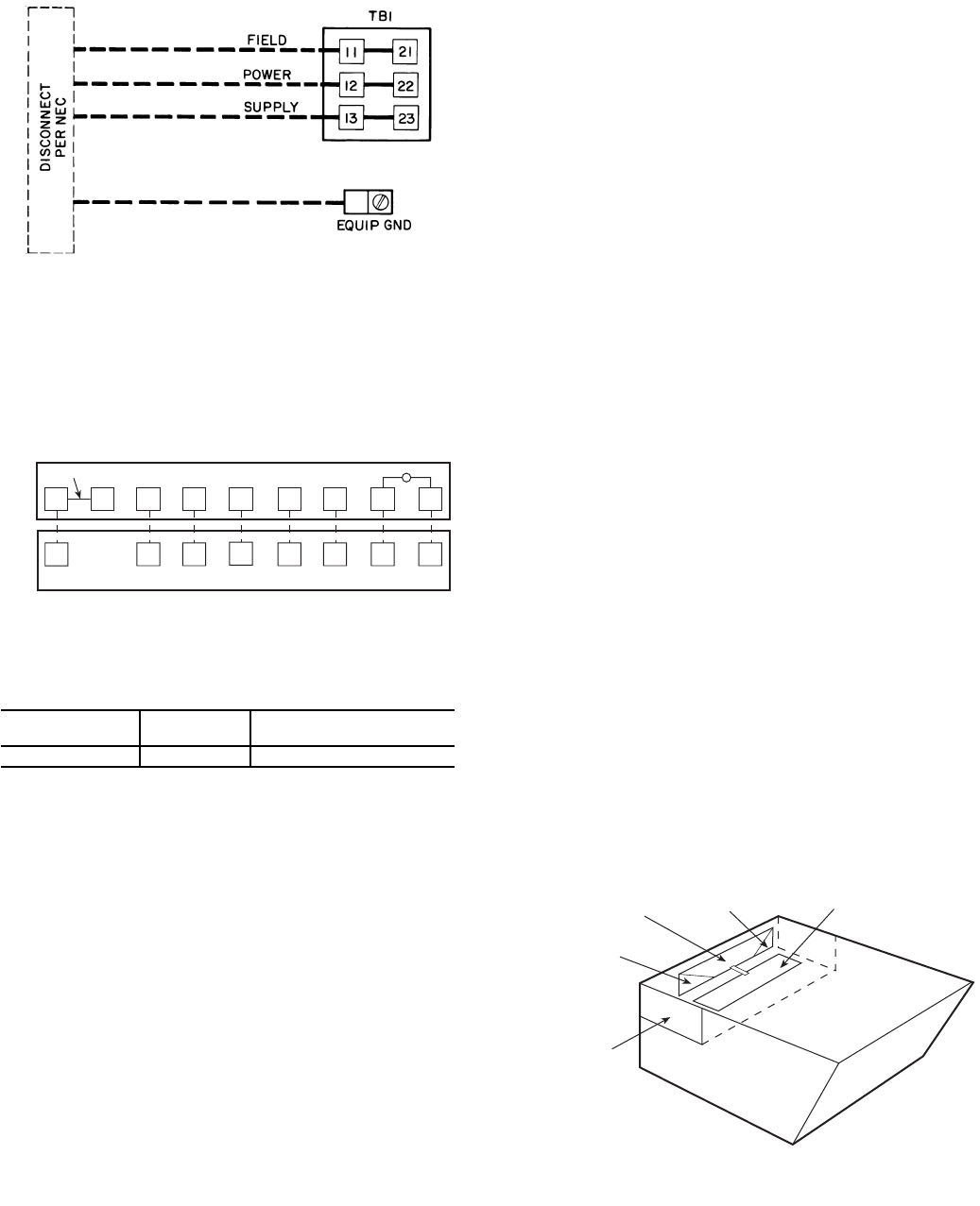
Step 10 — Install Outdoor Air Hood — Per-
form the following procedure to install the outdoor-air hood on
units equipped with an economizer, two-position damper, or
manual outdoor air damper:
1. Remove blank panel from return end of unit (hood sec-
tion). Save the screws. See Fig. 17 for shipping location
of components.
2. Hood sides are fastened to sides of outdoor air opening.
Remove the hood sides and save the screws (3 each side).
3. Remove the bracket holding the bottom half of the hood
in the shipping position. Remove the hood bottom half
and filters (or manual dampers on units so equipped)
from outdoor section.
NOTE: On units without economizers, the components
are attached to the unit basepan. To access the compo-
nents, remove the panel below the outdoor air intake
section.
4. Remove inner filter track from shipping position in out-
door section. Position inner filter track so the track is
facing outward from the unit. Install the filter track with 4
screws provided.
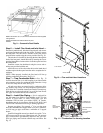
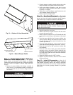
5. Apply seal strip (provided) to back flange of both hood
sides where hood side connects to the unit back panel.
See Fig. 18.
6. Apply seal strip (provided) to top flange of both hood
sides where hood sides connect to the hood top panels.
See Fig. 18.
7. Install hood sides to the back panels using the screws
from Step 2. The sloped flanges point outward. The drip
edges of the side panels should face outward as well. The
filter guides to the hood sides. The flanges of the filter
guides should face inward to hold the filters in place.
See Fig. 18.
8. Apply seal strip along the entire length of the bottom
flange of the hood top. See Fig. 18.
9. Install the bottom part of the hood top using 4 screws pro-
vided. See Fig. 18.
10. Remove the packaging from filters (3) and install into the
filter tracks. Slide the filters to the sides then place the last
filter into the center of the filter track.
NOTE: For units with manual dampers, replace the end filters
with the manual dampers. Install the filter in the center
between the manual dampers.
11. Install the filter retainer track along the bottom edge of
the outdoor air hood using 4 screws provided. See
Fig. 18.
12. Install top section of the outdoor air hood using 9 screws
provided. See Fig. 18. See Fig. 19 for a picture of the as-
sembled outdoor air hood.
NOTE: For filter removal, remove the four screws holding the
filter retainer. The filters can then be removed, cleaned, or
replaced. Install the filters by reversing the procedure.
MANUAL DAMPER ASSEMBLY — For units equipped
with manual dampers, the assembly process is similar to the
outdoor air hood for units with economizers. There are two
slide dampers shipped with the unit to allow for manual setting
of the outside air volume. When assembling the hood, place
one of the manual slide dampers in each of the end positions
and the remaining filter in the center position. The manual
dampers can then be moved to the appropriate position and
then locked into place using the screws mounted in the adjust-
ment slots. See Fig. 20.
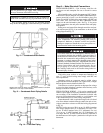
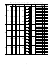
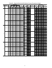
VOLTAGE
STAGE 1
(W1) ON
STAGE 1 AND 2
(W1 AND W2) ON
All 0.98 0.44
TB2-
J11
REMOVABLE JUMPER
1
2
3
45
6
7
8
THERMOSTATASSEMBLY
RH
RC
Y1 Y2
W1 W2 G C
L
X
R
Y1 Y2
W1 W2 G C X
LEGEND
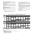
NOTE: The maximum wire size for TB1 is 2/0.
Fig. 15 — Field Power Wiring Connections
EQUIP — Equipment
GND — Ground
NEC — National Electrical Code
TB — Terminal Board
Fig. 16 — Field Control Thermostat Wiring
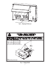
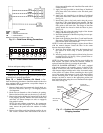
HOOD TOP
(BOTTOM HALF)
HOOD TOP
(TOPHALF)
HOOD
SIDE
HOOD
SIDE
RETURN AIR
SECTION
Fig. 17 — Outdoor-Air Hood Component
Shipping Location