


52
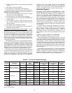
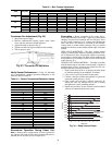
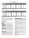
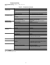
Table 32 — Altitude Compensation*
NATURAL GAS
*As the height above sea level increases, there is less oxygen per cubic foot of air. Therefore, heat input
rate should be reduced at higher altitudes. Includes a 4% input reduction per each 1000 ft.
†Orifices available through the local Carrier dealer.
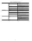
PROPANE GAS
*As the height above sea level increases, there is less oxygen per cubic foot of air. Therefore, heat input
ate should be reduced at higher altitudes. Includes a 4% input reduction per each 1000 ft.
†Orifices available through the local Carrier dealer.
Filter Drier — Replace whenever refrigerant system is ex-
posed to atmosphere. Only use factory specified liquid-line
filter driers with working pressures no less than 650 psig. Do
not install a suction-line filter drier in liquid line. A liquid-line
filter drier designed for use with Puron® refrigerant is required
for each circuit.
Protective Devices
COMPRESSOR PROTECTION
Overcurrent
— Each compressor has internal line break motor
protection.
Overtemperature
— Each compressor has an internal protector
to protect it against excessively high discharge gas temperatures.
High-Pressure Switch
— If the high-pressure switch opens, the
compressor will shut down and the compressor lockout (CLO)
device will energize to block further compressor operation. The
high-pressure switch will reset automatically as the refrigerant
pressure drops below its reset level. The CLO will remain ener-
gized until manually reset or cooling demand is removed.
Low-Pressure Switch
— If the low-pressure switch opens,
the compressor will shut down and the compressor lockout
(CLO) device will energize to block further compressor opera-
tion. The low-pressure switch will reset automatically as the
refrigerant pressure rises above its reset level. The CLO will
remain energized until manually reset or cooling demand is
removed.
Freeze Protection Switch
— This switch is installed on each
evaporator coil section to provide protection against continued
unit operation with a frosted evaporator surface. If the freeze
protection switch opens, the compressor on this circuit will
shut down and the compressor lockout (CLO) device will ener-
gize to block further compressor operation. The freeze protec-
tion switch will reset as the evaporator tube temperature rises
above its reset level. The CLO will remain energized until
manually reset or cooling demand is removed.
Compressor Lockout (CLO) Device
— The CLO prevents
automatic recycling of the compressor as safety controls reset.
If the high-pressure switch, low-pressure switch or freeze pro-
tection switch opens, the CLO device will energize to block
further compressor operation. To reset the CLO (after all safety
switches have reset), either open the thermostat to remove the
cooling demand signal (and then re-close) or cycle the control
power in the unit.
EVAPORATOR FAN MOTOR PROTECTION — A manu-
al reset, calibrated trip, magnetic circuit breaker protects
against overcurrent. Do not bypass connections or increase the
size of the breaker to correct trouble. Determine the cause and
correct it before resetting the breaker.
CONDENSER-FAN MOTOR PROTECTION — Each
condenser-fan motor is internally protected against
overtemperature.
Fuses are also located in the control box and feed power to
the condenser fan motors. Always replace blown fuses with the
correct size fuse as indicated on the unit fuse label.
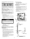
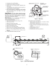
Relief Devices — All units have relief devices to protect
against damage from excessive pressures (i.e., fire). These
devices protect the high and low side and are located at the suc-
tion line service port. Protect joint during brazing operations
near joint.
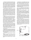
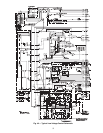
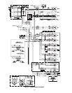
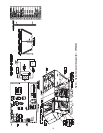
Control Circuit, 24-V — Each control circuit is pro-
tected against overcurrent by a 3.2 amp circuit breaker.
Breaker can be reset. If it trips, determine cause of trouble
before resetting. See Fig. 42-45 for schematics.
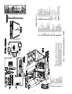
Replacement Parts — A complete list of replacement
parts may be obtained from any Carrier distributor upon
request.
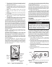
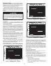
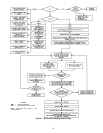
Diagnostic LEDs — The IGC control board has a LED
for diagnostic purposes. See Unit Troubleshooting section on
page 57 for more information.
ELEVATION
(ft)
NATURAL GAS ORIFICE SIZE†
Low Heat Medium Heat High Heat (6 Cell) High Heat (8 Cell)
0-1,999 29 30 29 29
2,000 29 30 29 29
3,000 30 31 30 30
4,000 30 31 30 30
5,000 30 31 30 30
6,000 30 31 30 30
7,000 31 32 31 31
8,000 31 32 31 31
9,000 31 32 31 31
10,000 32 33 32 32
ELEVATION
(ft)
PROPANE GAS ORIFICE SIZE†
Low Heat Medium Heat High Heat (6 Cell) High Heat (8 Cell)
0-1,999 35 38 35 35
2,000 36 39 36 36
3,000 36 39 36 36
4,000 37 40 37 37
5,000 37 40 37 37
6,000 38 41 38 38
7,000 39 42 39 39
8,000 40 43 40 40
9,000 41 44 41 41
10,000 42 45 42 42