


40
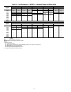
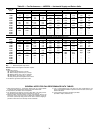
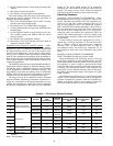
Table 28 — EconoMi$er IV Sensor Usage
*CRENTDIF004A00 and CRTEMPSN002A00 accessories are used on many different base units. As such, these kits may contain parts that will not be
needed for installation.
†33ZCSENCO2 is an accessory CO
2
sensor.
**33ZCASPCO2 is an accessory aspirator box required for duct-mounted applications.
††CRCBDIOX005A00 is an accessory that contains both 33ZCSENCO2 and 33ZCASPCO2 accessories.
APPLICATION
ECONOMI$ER IV WITH OUTDOOR AIR
DRY BULB SENSOR
ECONOMI$ER IV WITH SINGLE
ENTHALPY SENSOR
Accessories Required Accessories Required
Outdoor Air Dry Bulb None. The outdoor air dry bulb sensor is factory installed. CRTEMPSN002A00*
Differential Dry Bulb CRTEMPSN002A00* (2) CRTEMPSN002A00*
Single Enthalpy HH57AC078 None. The single enthalpy sensor is factory installed.
Differential Enthalpy
HH57AC078
and
CRENTDIF004A00*
CRENTDIF004A00*
CO
2
for DCV Control using a
Wall-Mounted CO
2
Sensor
33ZCSENCO2 33ZCSENCO2
CO
2
for DCV Control using a
Duct-Mounted CO
2
Sensor
33ZCSENCO2†
and
33ZCASPCO2**
OR
CRCBDIOX005A00††
33ZCSENCO2†
and
33ZCASPCO2**
OR
CRCBDIOX005A00††
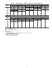
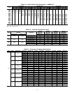
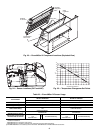
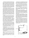
DAMPER
ACTUATOR
PL7
WIRE TIES
DAMPER
ASSEMBLY
WIRE
HARNESS
ECONOMIZER
BLOCK OFF
PL7
OUTSIDE AIR
ENTHALPY
INDOOR AIR
ENTHALPY
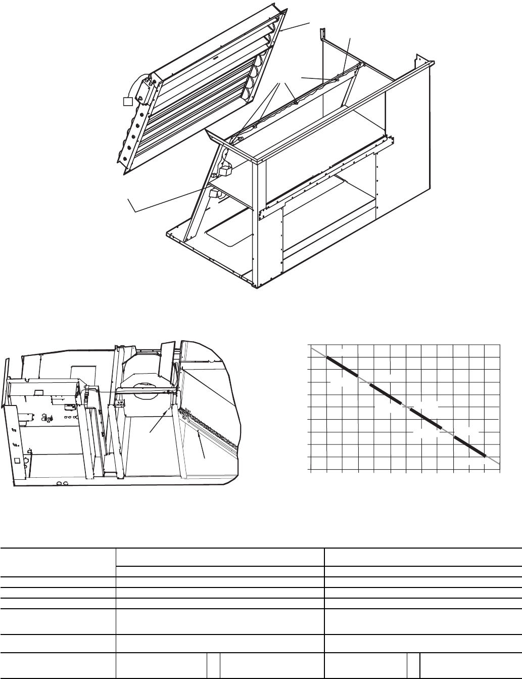
Fig. 23 — EconoMi$er IV Component Locations (Exploded View)
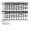
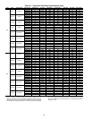
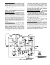
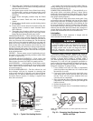
MAT LOCATION
OAT LOCATION
Fig. 24 — Sensor Locations (OAT and MAT)
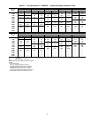
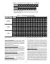
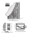
LED ON
LED ON
LED ON
LED ON
LED OFF
19
18
LED OFF
LED OFF
LED OFF
17
16
15
14
13
12
11
10
9
40
45
50
55
60
65
70
75
80
85
90
95
100
DEGREES FAHRENHEIT
mA
D
C
B
A
Fig. 25 — Temperature Changeover Set Points