


40
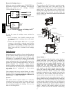
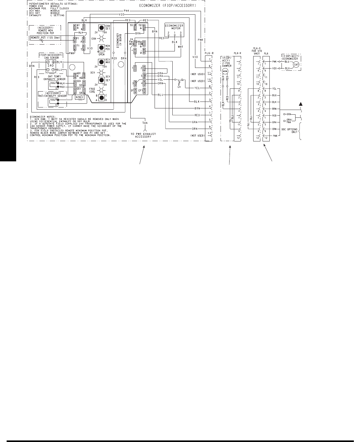
Economizer 2 Position Damper
Unit Without Economizer o
r
2 Position Damper
C10150
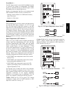
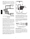
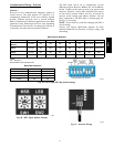
Fig. 62 -- EconoMi$ert IV Wiring
Step 13 — Adjust Factory--Installed Options
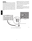
Smoke Detectors —
Smoke detector(s) will be connected at the Controls
Connections Board, at terminals marked “Smoke
Shutdown”. Remove jumper JMP 3 when ready to
energize unit.
EconoMi$er IV Occupancy Switch —
Refer to Fig. 62 for general EconoMi$er IV wiring.
External occupancy control is managed through a
connection on the Central Terminal Board.
If external occupancy control is desired, connect a time
clock or remotely controlled switch (closed for Occupied,
open for Unoccupied sequence) at terminals marked
OCCUPANCY on CTB. Remove or cut jumper JMP 2 to
complete the installation.
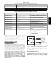
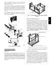
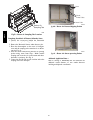
Step 14 — Install Accessories
Available accessories include:
Roof Curb
Thru--base connection kit (must be installed before unit
is set on curb)
LP conversion kit
Manual outside air damper
High Altitude Gas kits
Flue Discharge Deflector
Flue Exhaust Heat Shield
Low Ambient Controls
Thermostat / Sensors
Two--Position motorized outside air damper
EconoMi$er2 (without control/for external signal and
integrated barometric relief)
EconoMi$er2 (without control/for external signal)
Power Exhaust
Differential dry--bulb sensor (EconoMi$er IV)
Outdoor enthalpy sensor
Differential enthalpy sensor
CO
2
sensor
Louvered hail guard
Phase monitor control
Winter Start kit
Refer to separate installation instructions for information
on installing these accessories.
Pre--Start and Start--Up
This completes the mechanical installation of the unit.
Refer to the unit’s Service Manual for detailed Pre--Start
and Start--up instructions.
Copyright2011 Bryant Heating & Cooling Systems D 7310 W. Mo rris St. D Indianapolis, IN 46231 Printed in U.S.A. Edition Date: 04/11
Manufacturer reser ves the ri ght to change, at any time, specifications and designs without notice and without obligations.
Catalog No: II581J---10
Replaces: II581J---01 & II581J---03
581J