


28
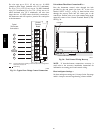
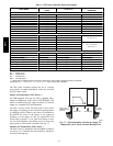
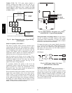
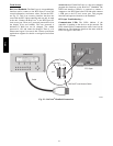
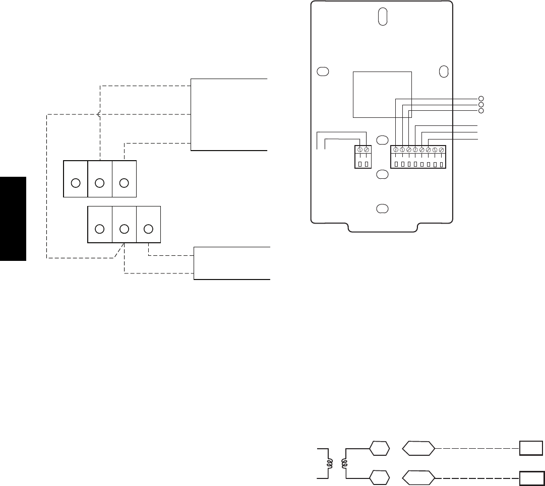
Connect T--59: The T--59 space sensor requires a
separate, isolated power supply of 24 VAC. See Fig. 42
for internal connections at the T--59. Connect the SEN
terminal (BLU) to RTU Open J20--1. Connect the COM
terminal (BRN) to J20--2. Connect the SET terminal (STO
or BLK) to J20--3.
OR SET SEN
OPB COM- PWR+
BLU (SPT)
BLK (STO)
24 VAC
SENSOR
WIRING
POWER
WIRING
BRN (COM)
NOTE: Must use a separate isolated transformer.
J20-3
J20-2
J20-1
C10291
Fig. 42 -- Space Temperature Sensor Typical Wiring
(33ZCT59SPT)
Indoor Air Quality (CO
2
)Sensor—
The indoor air quality sensor accessory monitors space
carbon dioxide (CO
2
) levels. This information is used to
monitor IAQ levels. Several types of sensors are available,
for wall mounting in the space or in return duct, with and
without LCD display, and in combination with space
temperature sensors. Sensors use infrared technology to
measure the levels of CO
2
present in the space air.
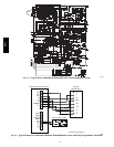
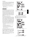
The CO
2
sensors are all factory set for a range of 0 to
2000 ppm and a linear mA output of 4 to 20. Refer to the
instructions supplied with the CO
2
sensor for electrical
requirements and terminal locations. See Fig. 43 for
typical CO
2
sensor wiring schematic.
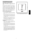
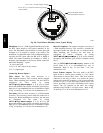
To accurately monitor the quality of the air in the
conditioned air space, locate the sensor near a return--air
grille (if present) so it senses the concentration of CO
2
leaving the space. The sensor should be mounted in a
location to avoid direct breath contact.
Do not mount the IAQ sensor in drafty areas such as near
supply ducts, open windows, fans, or over heat sources.
Allow at least 3 ft (0.9 m) between the sensor and any
corner. Avoid mounting the sensor where it is influenced
by the supply air; the sensor gives inaccurate readings if
the supply air is blown directly onto the sensor or if the
supply air does not have a chance to mix with the room air
before it is drawn into the return airstream.
8
7
6
5
4
32
1
2
1
HG
24 VAC
OR
24 VDC
NC
ALARM
RELAY
CONTACTS
COM
NO
}
0-10VDC
SIG COM
4-20mA
+
+
-
+
-
J3 J4
C08635
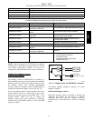
Fig. 43 -- Indoor/Outdoor Air Quality (CO
2
)Sensor
(33ZCSENCO2) -- Typical Wiring Diagram
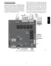
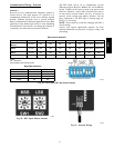
Wiring the Indoor Air Quality Sensor: For each sensor,
use two 2--conductor 18 AWG (American Wire Gage)
twisted--pair cables (unshielded) to connect the separate
isolated 24 vac power source to the sensor and to connect
the sensor to the control board terminals.
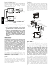
To connect the sensor to the control, identify the positive
(4 to 20 mA) and ground (SIG COM) terminals on the
sensor. See Fig. 43. Connect the 4--20 mA terminal to
RTU Open J4--2 and connect the SIG COM terminal to
RTU Open J4--3. See Fig. 44.
SEN
COM
J4-2
J4-3
IAQ Sensor
24 VAC
C08462
Fig. 44 -- RTU Open / Indoor CO
2
Sensor
(33ZCSENCO2) Connections
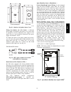
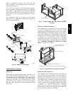
Outdoor Air Quality Sensor
(PNO 33ZCSENCO2 plus weatherproof enclosure) —
The outdoor air CO
2
sensor is designed to monitor carbon
dioxide (CO
2
) levels in the outside ventilation air and
interface with the ventilation damper in an HVAC system.
The OAQ sensor is packaged with an outdoor cover. See
Fig. 45. The outdoor air CO
2
sensor must be located in the
economizer outside air hood.
581J