


16
NOTE: Pressure test the gas supply system after the gas
supply piping is connected to the gas valve. The supply
piping must be disconnected from the gas valve during the
testing of the piping systems when test pressure is in
excess of 0.5 psig (3450 Pa). Pressure test the gas supply
piping system at pressures equal to or less than 0.5 psig
(3450 Pa). The unit heating section must be isolated from
the gas piping system by closing the external main manual
shutoff valve and slightly opening the ground--joint union.
Check for gas leaks at the field--installed and
factory--installed gas lines after all piping connections
have been completed. Use soap--and--water solution (or
method specified by local codes and/or regulations).
FIRE OR EXPLOSION HAZARD
Failure to follow this warning could result in personal
injury, death and/or property damage.
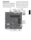
S Connect gas pipe to unit using a backup wrench to
avoid damaging gas controls.
S Never purge a gas line into a combustion chamber.
S Never test for gas leaks with an open flame. Use a
commercially available soap solution made
specifically for the detection of leaks to check all
connections.
S Use proper length of pipe to avoid stress on gas
control manifold.
!
WARNING
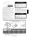
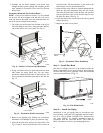
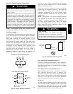
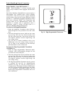
NOTE: If orifice hole appears damaged or it is suspected
to have been redrilled, check orifice hole with a numbered
drill bit of correct size. Never redrill an orifice. A
burr--free and squarely aligned orifice hole is essential for
proper flame characteristics.
BURNER
ORIFICE
A93059
Fig. 21 -- Orifice Hole
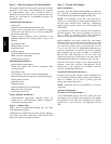
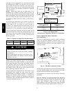
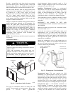
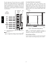
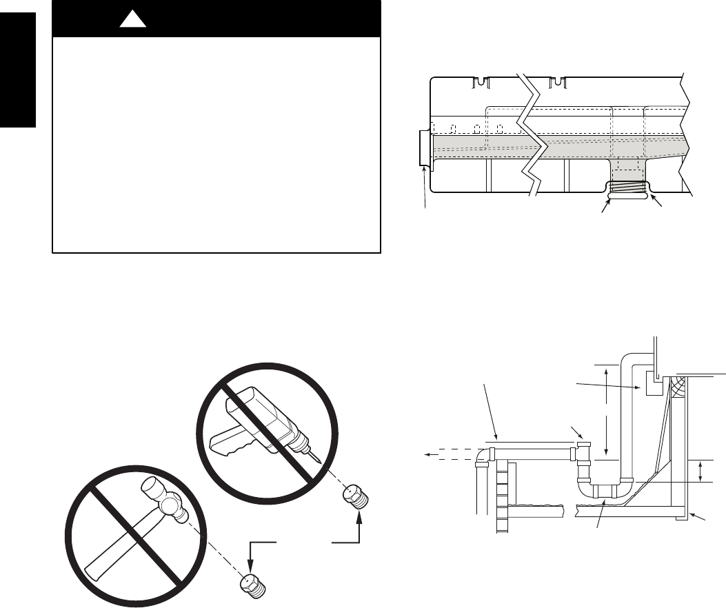
Step 11 — Install External Condensate Trap and
Line
The unit has one
3
/
4
-in. condensate drain connection on
the end of the condensate pan and an alternate connection
on the bottom. See Fig. 22. Unit airflow configuration
does not determine which drain connection to use. Either
drain connection can be used with vertical or horizontal
applications.
When using the standard side drain connection, ensure the
red plug in the alternate bottom connection is tight. Do
this before setting the unit in place. The red drain pan can
be tightened with a
1
/
2
--in. square socket drive extension.
To use the alternate bottom drain connection, remove the
red drain plug from the bottom connection (use a
1
/
2
-- i n .
square socket drive extension) and install it in the side
drain connection.
DRAIN
(FACTORY-INSTALLED)
PLUG
CONDENSATE PAN (SIDE VIEW)
STANDARD
SIDE DRAIN
ALTERNATE
BOTTOM DRAIN
C08021
Fig. 22 -- Condensate Drain Pan (Side View)
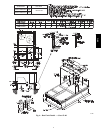
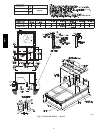
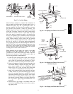
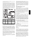
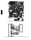
The piping for the condensate drain and external trap can
be completed after the unit is in place. See Fig. 23.
NOTE: Trap should be deep enough to offset maximum unit static
difference. A 4” (102) trap is recommended.
MINIMUM PITCH
1” (25mm) PER
10’ (3m) OF LINE
BASE RAIL
OPEN
VENT
TO ROOF
DRAIN
DRAIN PLUG
ROOF
CURB
SEE NOTE
2˝ (51) MIN
C08022
Fig. 23 -- Condensate Drain Piping Details
All units must have an external trap for condensate
drainage. Install a trap at least 4-in. (102 mm) deep and
protect against freeze-up. If drain line is installed
downstream from the external trap, pitch the line away
from the unit at 1-in. per 10 ft (25 mm in 3 m) of run. Do
not use a pipe size smaller than the unit connection
(
3
/
4
-in.).
581J