


20
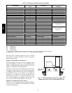
For wire runs up to 50 ft. (15 m), use no. 18 AWG
(American Wire Gage) insulated wire (35_C minimum).
For50to75ft.(15to23m),useno.16AWGinsulated
wire (35_C minimum). For over 75 ft. (23 m), use no. 14
AWG insulated wire (35_C minimum). All wire sizes
larger than no. 18 AWG cannot be directly connected to
the thermostat and will require a junction box and splice
at the thermostat.
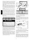
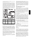
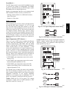
Typical
Thermostat
Connections
Central
Terminal
Board
W1
Y2
Y1
R
W2
G
C
X
W1
Y2
Y1
R
W2
G
C
X
T–STAT
C
W2
G
W1
O/B/Y2
R
Y1
(see Note)
Note : Typical multi-function marking. Follow manufacturer’s configuration
instructions to select Y2.
Field Wiring
C09350
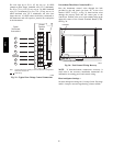
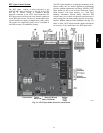
Fig. 29 -- Typical Low--Voltage Control Connections
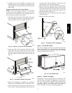
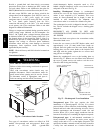
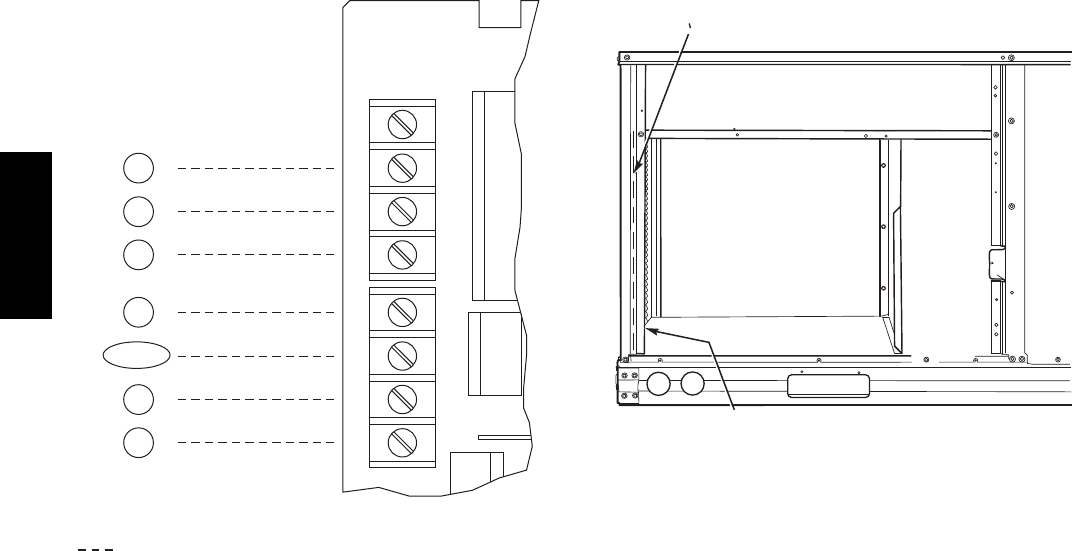
Unit without Thru--Base Connection Kit —
Pass the thermostat control wires through the hole
provided in the end panel (see item “D” in the view
labeled “LEFT” in Fig. 1 or Fig. 2); then feed the wires
through the raceway built into the corner post to the
control box. Pull the wires over to the terminal strip on the
upper--left corner of the Central Terminal Board (CTB).
See Fig. 30.
RACEWAY
HOLE IN END PANEL (HIDDEN)
C08027
Fig. 30 -- Field Control Wiring Raceway
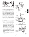
NOTE: If thru--the--bottom connections accessory is
used, refer to the accessory installation instructions for
information on routing power and control wiring.
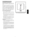
Heat Anticipator Settings —
Set heat anticipator settings at 0.14 amp for the first stage
and 0.14 amp for second--stage heating, when available.
581J