


14
This unit is factory equipped for use with Natural Gas fuel
at elevations up to 2000 ft (610 m) above sea level. Unit
may be field converted for operation at elevations above
2000 ft (610 m) and/or for use with liquefied petroleum
fuel. See accessory kit installation instructions regarding
these accessories.
NOTE: Furance gas input rate on rating plate is for
installation up to 2000 ft (610 m) above sea level. In
U.S.A. the input rating for altitudes above 2000 ft (610 m)
must be derated by 4% for each 1000 ft (305 m) above sea
level. In Canada the input rating must be derated by 10%
for altitudes of 2000 ft (610 m) to 4500 ft (1372 m) above
sea level.
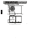
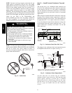
For natural gas applications, gas pressure at unit gas
connection must not be less than 4 in. wg (996 Pa) or
greater than 13 in. wg (3240 Pa) while the unit is
operating. For liquified petroleum applications, the gas
pressure must not be less than 11 in. wg (2740 Pa) or
greater than 13 in. wg (3240 Pa) at the unit connection.
The gas supply pipe enters the unit at the burner access
panel on the front side of the unit, through the long slot at
the bottom of the access panel. The gas connection to the
unit is made to the
1
/
2
-- i n . o r
3
/
4
--in. FPT gas inlet port on
the unit gas valve.
Table 2 – Natural Gas Supply Line Pressure Ranges
UNIT MODEL UNIT SIZE MIN MAX
581J 07, 08, 09, 12
4.0 in. wg
(996 Pa)
13.0 in. wg
(3240 Pa)
EQUIPMENT DAMAGE HAZARD
Failure to follow this caution may result in damage
to equipment.
When connecting the gas line to the unit gas valve,
the installer MUST use a backup wrench to prevent
damage to the valve.
CAUTION
!
Install a gas supply line that runs to the unit heating
section. Refer to the NFPA 54/NFGC or equivalent code
for gas pipe sizing data. Do not use a pipe smaller than the
size specified. Size the gas supply line to allow for a
maximum pressure drop of 0.5--in wg (124 Pa) between
gas regulator source and unit gas valve connection when
unit is operating at high--fire flow rate.
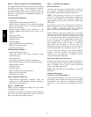
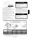
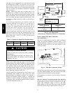
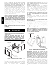
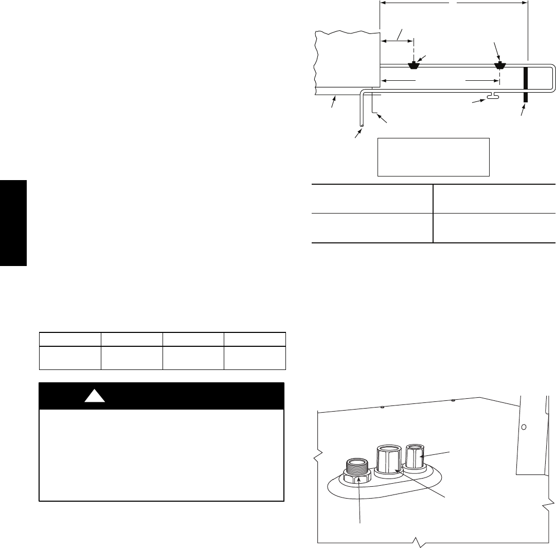
The gas supply line can approach the unit in three ways:
horizontally from outside the unit (across the roof),
thru--curb/under unit basepan (accessory kit required) or
through unit basepan (factory--option or accessory kit
required). Consult accessory kit installation instructions
for details on these installation methods. Observe clearance
to gas line components per Fig. 15.
LEGEND
*
Field supplied.
NOTE: Follow all local codes.
NFGC – National Fuel Gas Code
STEEL PIPE
NOMINAL DIAMETER
(in.)
SPACINGOFSUPPORTS
X DIMENSION
(ft)
1
/
2
3
/
4
or 1
1
1
/
4
or larger
6
8
10
X
BASE UNIT
BASE RAIL
ROOF
CURB
9” MINIMUM CLEARANCE
FOR PANEL REMOVAL
MANUAL GAS
SHUTOFF VALVE
*
GAS
REGULATOR
*
48” MINIMUM
DRIP LEG
PER NFGC
*
FIELD-FABRICATED
SUPPORT
*
FROM
GAS
METER
C11091
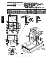
Fig. 15 -- Gas Piping Guide
(with Accessory Thru--the--Curb Service Connections)
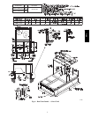
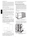
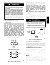
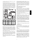
Factory--Option Thru--Base Connections
(Gas Connections) —
This service connection kit consists of a NPT gas adapter
fitting, an electrical bulkhead connector and a
3
/
4
-- i n
electrical bulkhead connector, all factory--installed in the
embossed (raised) section of the unit basepan in the
condenser section.
LOW VOLTAGE
CONDUIT
CONNECTOR
STAINLESS STEEL FITTING
HIGH VOLTAGE
CONDUIT
CONNECTOR
C008621
Fig. 16 -- Thru--Base Connection Fittings
The thru--base gas connector has male and female threads.
The male threads protrude above the basepan of the unit;
the female threads protrude below the basepan.
Check tightness of connector lock nuts before connecting
gas piping.
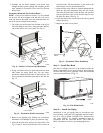
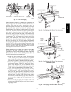
Gas Line: Install a
1
/
2
--in (08 & 09 size Low Gas units
only) or
3
/
4
--in (for all other units) NPT street elbow on
the thru--base gas fitting. Attach an appropriate size pipe
nipple with minimum length of 16--in (406 mm)
(field--supplied) to the street elbow and extend it through
the access panel at the gas support bracket. See Fig. 17.
581J