


19
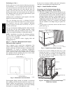
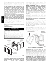
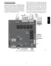
convenience outlet; access is through the unit’s control
box access panel. See Fig. 26.
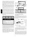
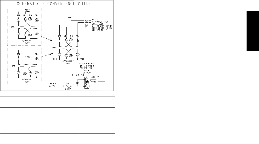
The primary leads to the convenience outlet transformer are
not factory--connected. Selection of primary power source is
a customer--option. If local codes permit, the transformer
primary leads can be connected at the line--side terminals on
the unit--mounted non--fused disconnect or HACR breaker
switch; this will provide service power to the unit when the
unit disconnect switch or HACR switch is open. Other
connection methods will result in the convenience outlet
circuit being de--energized when the unit disconnect or
HACR switch is open. See Fig. 28.
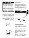
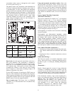
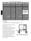
C08283
UNIT
VOLTAGE
CONNECT
AS
PRIMARY
CONNECTIONS
TRANSFORMER
TERMINALS
208,
230
240
L1: RED +YEL
L2: BLU + GRA
H1 + H3
H2 + H4
460 480
L1: RED
Splice BLU + YEL
L2: GRA
H1
H2 + H3
H4
575 600
L1: RED
L2: GRA
H1
H2
Fig. 28 -- Powered Convenience Outlet Wiring
Duty Cycle: the unit--powered convenience outlet has a
duty cycle limitation. The transformer is intended to
provide power on an intermittent basis for service tools,
lamps, etc; it is not intended to provide 15--amps loading
for continuous duty loads (such as electric heaters for
overnight use). Observe a 50% limit on circuit loading
above 8--amps (i.e., limit loads exceeding 8--amps to 30
minutes of operation every hour).
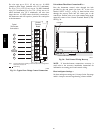
Test the GFCI receptacle by pressing the TEST button on
the face of the receptacle to trip and open the receptacle.
Check for proper grounding wires and power line phasing
if the GFCI receptacle does not trip as required. Press the
RESET button to clear the tripped condition.
Fuse on power type: The factory fuse is a Bussman
“Fusetron” T--15, non--renewable screw--in (Edison base)
type plug fuse.
Using unit--mounted convenience outlets: Units with
unit--mounded convenience outlet circuits will often
require that two disconnects be opened to de--energize all
power to the unit. Treat all units as electrically energized
until the convenience outlet power is also checked and
de--energization is confirmed. Observe National Electrical
Code Article 210, Branch Circuits, for use of convenience
outlets.
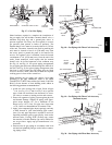
Factory--Option Thru--Base Connections
(Electrical Connections) —
This service connection kit consists of a
1
/
2
--in electrical
bulkhead connector and a 1
1
/
4
--in electrical bulkhead
connector, all factory--installed in the embossed (raised)
section of the unit basepan in the condenser section. The
1
/
2
--in bulkhead connector enables the low--voltage control
wires to pass through the basepan. The 1
1
/
4
--in electrical
bulkhead connector allows the high--voltage power wires
to pass through the basepan. See Fig. 16.
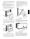
Check tightness of connector lock nuts before connecting
electrical conduits.
Field--supplied and field--installed liquidtight conduit
connectors and conduit may be attached to the connectors on
the basepan. Pull correctly rated high voltage and low
voltage through appropriate conduits. Connect the power
conduit to the internal disconnect (if unit is so equipped) or
to the external disconnect (through unit side panel). A hole
must be field cut in the main control box bottom on the left
side so the 24--v control connections can be made. Connect
the control power conduit to the unit control box at this hole.
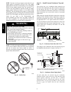
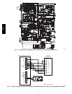
Units without Thru--Base Connections —
1. Install power wiring conduit through side panel open-
ings. Install conduit between disconnect and control
box.
2. Install power lines to terminal connections as shown
in Fig. 24.
Field Control Wiring —
The 581J unit requires an external temperature control
device. This device can be a thermostat emulation device
provided as part of a third--party Building Management
System.
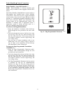
Thermostat —
Install a Bryant--approved accessory 2--stage thermostat
according to installation instructions included with the
accessory. Locate the thermostat accessory on a solid wall
in the conditioned space to sense average temperature in
accordance with the thermostat installation instructions.
If the thermostat contains a logic circuit requiring 24--v
power, use a thermostat cable or equivalent single leads of
different colors with minimum of seven leads. If the
thermostat does not require a 24--v source (no “C”
connection required), use a thermostat cable or equivalent
with minimum of six leads. Check the thermostat
installation instructions for additional features which
might require additional conductors in the cable.
581J