


29
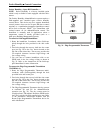
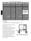
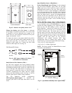
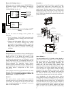
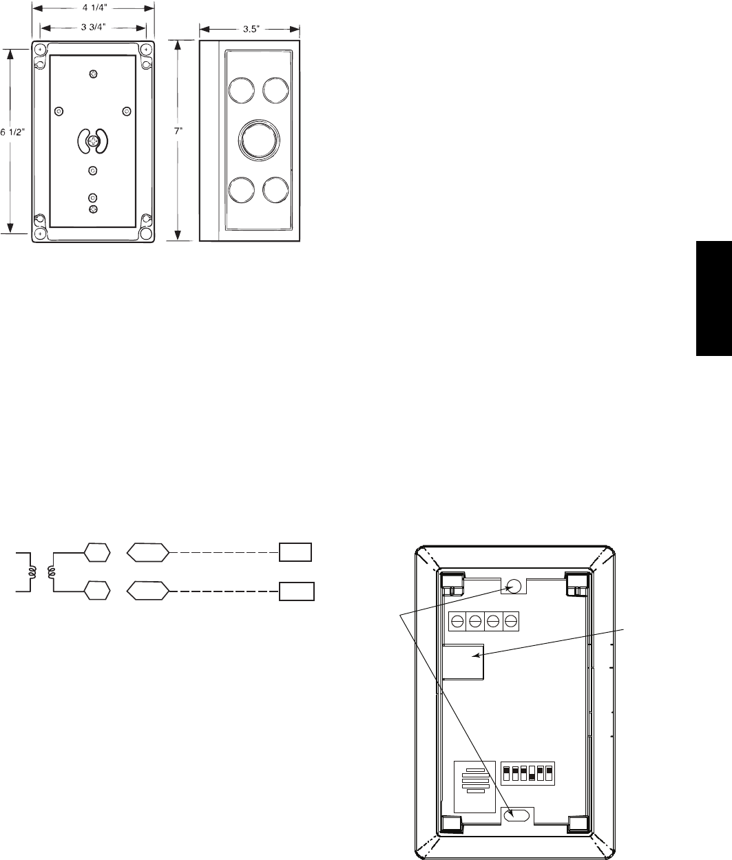
COVER REMOVED SIDE VIEW
C07135
Fig. 45 -- Outdoor Air Quality Sensor Cover
Wiring the Outdoor Air CO
2
Sensor: A dedicated
power supply is required for this sensor. A two--wire cable
is required to wire the dedicated power supply for the
sensor. The two wires should be connected to the power
supply and terminals 1 and 2.
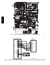
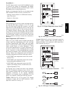
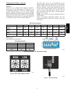
To connect the sensor to the control, identify the positive
(4 to 20 mA) and ground (SIG COM) terminals on the
OAQ sensor. See Fig. 43. Connect the 4 to 20 mA
terminal to RTU Open J4--5. Connect the SIG COM
terminal to RTU Open J4--6. See Fig. 46.
SEN
COM
J4-5
J4-6
OAQ Sensor/RH Sensor
24 VAC
C08463
Fig. 46 -- RTU Open / Outdoor CO
2
Sensor
(33ZCSENCO2) Connections
Smoke Detector/Fire Shutdown (FSD) —
On 581J units equipped with factory--installed Smoke
Detector(s), the smoke detector controller implements the
unit shutdown through its NC contact set connected to the
unit’s CTB input. The FSD function is initiated via the
smoke detector’s Alarm NO contact set. The RTU Open
controller communicates the smoke detector’s tripped
status to the BAS building control. See Figs. 35 and 36,
the RTU Open System Control wiring schematics.
The Fire Shutdown Switch configuration,
MENU
→
Config
→
Inputs
→
input 5, identifies the
normally open status of this input when there is no fire
alarm.
Space Humidity Sensor or Humidistat —
Perfect Humidityt Control Wiring: In units equipped
with the Perfect Humidity option there are two pink
(PNK) wires loose in the control box used to control the
dehumidification function of the unit. These pink wires
are meant to be tied to a space humidistat or thermidistat
on an electromechanical unit. On RTU Open equipped
units these pink wires must be connected to J11--7 & 8 to
allow the Open board to operate the dehumidification
function for the unit. Disconnect the J11 Phoenix style
connector from the board and use the plug screws to
secure the pink wires in pins 7 and 8, reconnect the plug
to the board at J11.
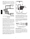
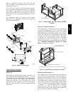
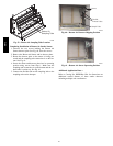
Relative Humidity Sensors (Space or Duct Mounted):
The accessory space humidity sensor (33ZCSENSRH-01)
or duct humidity sensor (33ZCSENDRH-01) is used to
measure the relative humidity of air within the space or
return air duct. The RH reading is used to control the
Perfect Humidityt option of the rooftop unit. For wiring
distances up to 500 ft (152 m), use a 3--conductor, 18 or
20 AWG shielded cable. The shield must be removed
from the sensor end of the cable and grounded at the unit
end. The current loop power for sensor is provided by the
RTU Open controller as 24vdc. Refer to the instructions
supplied with the RH sensor for the electrical
requirements and terminal locations. RTU Open
configurations must be changed after adding an RH
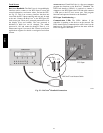
sensor. See Fig. 47 and 48 for typical RH sensor wiring.
S J4--1 or J4--4 = 24vdc loop power
S J4--2 or J4--5 = 4--20mA signal input
NOTE: The factory default for dehumidification control
is normally open humidistat.
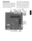
SW2
123456
ON
Io
Vin
Gnd
Vo
MOUNTING
HOLES
WIRING
OPENING
Vin - J4-1 or J4-4 24Vdc
Io - J4-2 or J4-5 -20mA output
C11087
Fig. 47 -- Space Relative Humidity Sensor Typical Wiring
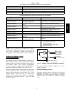
581J