


30
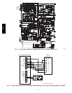
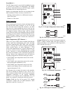
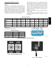
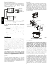
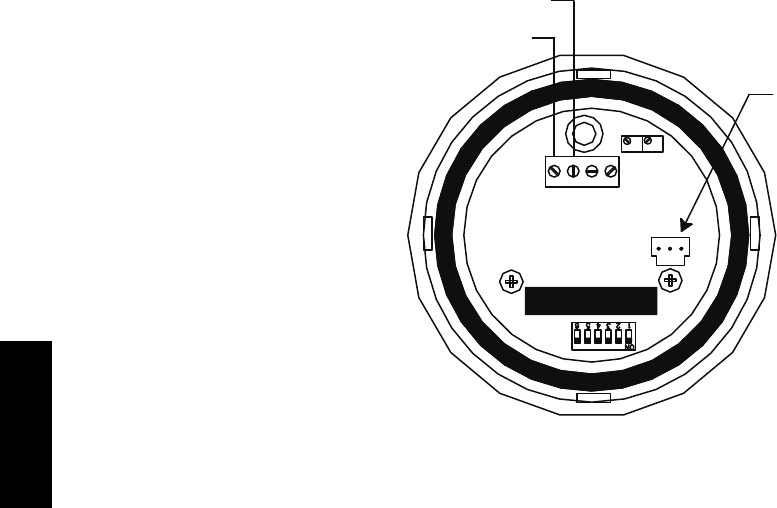
Relative Humidity Sensor
(Polarized Male Connector)
J4-1 or J4-4 + 24 VDC Supply Voltage
J4-2 or J4-5 (-) 4 to 20 mA Current Loop Output
to RTU-OPEN
4-20 VAC GND 0-5V
mA or or
VDC 0-10V
SPAN
ZERO
C10839
Fig. 48 -- Duct Relative Humidity Sensor Typical Wiring
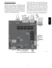
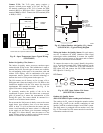
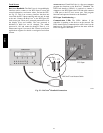
Humidistat: Use of a field--supplied humidistat provides
the RTU Open insight to the relative humidity in the
space. The humidistat reads the RH level in the space and
compares it to its setpoint to operate a dry contact. The
humidistat is a dedicated input on the configurable input 9
and tells the RTU Open when the RH level is HIGH or
LOW. The normal condition for humidity is LOW. A
normally open humidistat is the factory default control for
the Perfect Humidityt option.
To wire in the field:
S J5--8 = 24 VAC source for dry contact
S J5--7 = Signal input
Connecting Discrete Inputs —
Filter Status: The filter status accessory is a
field--installed accessory. This accessory detects plugged
filters. When installing this accessory, the unit must be
configured for filter status by setting
MENU
→
Config
→
Inputs
→
input3,5,8,or9to Filter
Status and normally open (N/O) or normally closed (N/C).
Input 8 or 9 is recommended for easy of installation. Refer
to Fig. 34 and Figs. 35 or 36 for wire terminations at J5.
Fan Status: The fan status accessory is a field--installed
accessory. This accessory detects when the indoor fan is
blowing air. When installing this accessory, the unit must
be configured for fan status by setting
MENU
→
Config
→
Inputs
→
input3,5,8,or9to Fan
Status and normally open (N/O) or normally closed (N/C).
Input 8 or 9 is recommended for easy of installation. Refer
to Fig. 34 and Figs. 35 or 36 for wire terminations at J5.
Remote Occupancy: The remote occupancy accessory is
a field--installed accessory. This accessory overrides the
unoccupied mode and puts the unit in occupied mode.
When installing this accessory, the unit must be
configured for remote occupancy by setting
MENU
→
Config
→
Inputs
→
input3,5,8,or9to Remote
Occupancy and normally open (N/O) or normally closed
(N/C).
Also set MENU
→
Schedules
→
occupancy source to DI
on/off. Input 8 or 9 is recommended for easy of
installation. Refer to Fig. 34 and Table 3 for wire
terminations at J5.
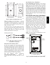
Power Exhaust (output): The relay used by the RTU
Open board to control power exhaust is a dry contact
which means it does not have 24vac. This 24vac must be
connected to the relay to allow it to operate the power
exhaust relay in the PE accessory. A 24vac source must be
provided to J11--2 on the RTU Open control board. This
can be provided by the unit’s transformer from various
sources. The “R” terminal on the unit’s low voltage
terminal board (LVTB) is a logical source. Refer to Fig.
34 and Figs. 35 or 36 for wire terminations at J11.
581J