


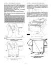

III. STEP 3 — FIELD FABRICATE DUCTWORK
Secure all ducts to building structure. Use flexible duct con-
nectors between unit and ducts as required. Insulate and weath-
erproof all external ductwork, joints, and roof openings with
counter flashing and mastic in accordance with applicable codes.
Ducts passing through an unconditioned space must be in-
sulated and covered with a vapor barrier.
The 559F units with electric heat require a 1-in. clearance
for the first 24 in. of ductwork.
Outlet grilles must not lie directly below unit discharge.
NOTE: A 90-degree elbow must be provided in the ductwork
to comply with UL (Underwriters’ Laboratories) codes for use
with electric heat.
WARNING:
For vertical supply and return units, tools
or parts could drop into ductwork and cause an injury.
Install a 90 degree turn in the return ductwork be-
tween the unit and the conditioned space. If a 90 de-
gree elbow cannot be installed, then a grille of sufficient
strength and density should be installed to prevent ob-
jects from falling into the conditioned space. Due to elec-
tric heater, supply duct will require 90 degree elbow.
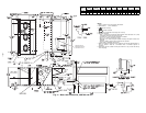
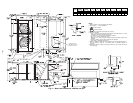
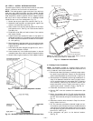
IV. STEP 4 — MAKE UNIT DUCT CONNECTIONS
Unit is shipped for thru-the-bottom duct connections. Duct-
work openings are shown in Fig. 6. Field-fabricated concen-
tric ductwork may be connected as shown in Fig. 7 and 8.
Attach all ductwork to roof curb and roof curb basepans. Re-
fer to installation instructions shipped with accessory roof curb
for more information.
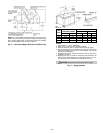
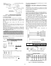
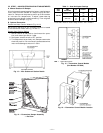
V. STEP 5 — TRAP CONDENSATE DRAIN
See Fig. 4, 5, and 9 for drain location. Plug is provided in
drain hole and must be removed when unit is operating. One
3
⁄
4
-in. half coupling is provided inside unit evaporator section
for condensate drain connection. An 8
1
⁄
2
in. x
3
⁄
4
-in. diameter
nipple and a 2-in. x
3
⁄
4
-in. diameter pipe nipple are coupled to
standard
3
⁄
4
-in. diameter elbows to provide a straight path
down through holes in unit base rails (see Fig. 10). A trap at
least 4-in. deep must be used.
NOTE: Do not drill in this area, as damage to basepan may result in
water leak.
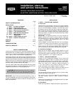
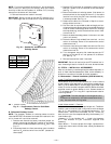
Fig. 6 — Air Distribution — Thru-the-Bottom
(559F216-300 Shown)
NOTE: Do not drill in this area, as damage to basepan may result in
water leak.
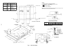
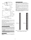
Fig. 7 — Concentric Duct Air Distribution
(559F216-300 Shown)
Shaded area indicates block-off panels.
NOTE: Dimension A, AЈ and B, BЈ are obtained from field-supplied ceil-
ing diffuser.
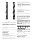
Fig. 8 — Concentric Duct Details
3/4" FPT DRAIN
CONNECTION
1-3/8"
DRAIN HOLES
Fig. 9 — Condensate Drain Details
(559F180,216 Shown)
—7—