


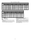
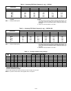
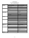
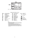


Table 11 — Economizer Checkout Procedures
TEST PROCEDURE RESULTS
A. Disconnect power at TR
and TR1.
Disconnect jumper
between P and
P1. See Fig. 15.
B. Jumper TR to 1.
C. Jumper T1 to T.
D. Disconnect outdoor-air
thermostat connections
from S
O
and +.
Factory-installed
800 ohm resistor
should remain connected
to S
R
and +.
E. Reconnect power to
terminals TR and TR1.
1. LED (light-emitting diode)
should be off.
2. Motor is in closed position.
TEST PROCEDURE RESULTS
A. Disconnect
factory-installed
resistor from
terminals S
R
and +.
1. LED (light-emitting diode)
should be on.
2. Motor drives toward open.
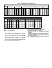
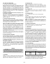
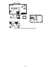
Table 12 — High and Low Outdoor-Air
Temperature Simulation
TEST PROCEDURE RESULTS
A. Reconnect factory-
installed 800 ohm resis-
tor between terminals
S
R
and +.
B. Connect 1200 ohm
checkout resistor
between terminals
S
O
and +.
C. Turn set point poten-
tiometer to position A.
Low outdoor-air temperature
test results:
1. LED (light-emitting diode)
should be on.
2. Motor drives toward open.
D. Turn set point poten-
tiometer to position D.
E. Disconnect 1200 ohm
checkout resistor.
High outdoor-air temperature
test results:
1. LED should be off.
2. Motor drives toward closed.
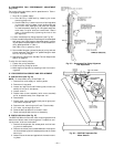
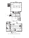
5. Set the outdoor-air thermostat (OAT) located in the econo-
mizer section of the unit (see Fig. 14) to 75 F.
6. If the outdoor temperature is below 75 F, the econo-
mizer will control the mixed air with the mixed-air sen-
sor. If the outdoor air is above 75 F, place a jumper
around the contacts of the OAT.
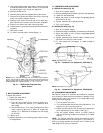
7. Jumper terminal T to terminal T1 on the module (see
Fig. 15). The economizer will go to the full open posi-
tion. The outdoor-air damper will go to the full open
position, and the return-air damper will go to the full
closed position.
8. Adjust mechanical linkage, if necessary, for correct po-
sitioning. It may be necessary to remove the filters to
adjust the linkage.
9. Remove the jumper from around the contacts of the OAT
if installed in Step 6. Remove the jumper from termi-
nals T and T1 installed in Step 7.
10. If the Cooling mode was simulated to operate the unit
in Step 4, remove the jumper and reconnect the ther-
mostat wires to terminals Y1 and Y2.
VIII. POWER FAILURE
Dampers have a spring return. In event of power failure, damp-
ers will return to fully closed position until power is restored.
Do not manually operate damper motor.
IX. REFRIGERANT CHARGE
Amount of refrigerant charge is listed on unit nameplate and
in Table 1. Refer to GTAC II; Module 5; Charging, Recovery,
Recycling, and Reclamation section for charging methods and
procedures. Unit panels must be in place when unit is oper-
ating during charging procedure.
NOTE: Do not use recycled refrigerant as it may contain
contaminants.
A. No Charge
Use standard evacuating techniques. After evacuating
system, weigh in the specified amount of refrigerant (refer to
Table 1).
B. Low Charge Cooling
Using cooling charging chart (see Fig. 30), add or remove re-
frigerant until conditions of the chart are met. Note that charg-
ing chart is different from those normally used. An accurate
pressure gage and temperature-sensing device is required.
Charging is accomplished by ensuring the proper amount of
liquid sub-cooling. Measure liquid line pressure at the liquid
line service valve using pressure gage. Connect temperature
sensing device to the liquid line near the liquid ine service
valve and insulate it so that outdoor ambient temperature
does not affect reading.
C. To Use the Cooling Charging Chart
Use the above temperature and pressure readings, and find
the intersection point on the cooling charging chart. If inter-
section point on chart is above line, add refrigerant. If inter-
section point on chart is below line, carefully recover some of
the charge. Recheck suction pressure as charge is adjusted.
NOTE: Indoor-air CFM must be within normal operating range
of unit. All outdoor fans must be operating.
The TXV (thermostatic expansion valve) is set to maintain
between 15 and 20 degrees of superheat at the compressors.
The valves are factory set and should not require
re-adjustment.
X. FILTER DRIER
Replace whenever refrigerant system is exposed to
atmosphere.
XI. PROTECTIVE DEVICES
A. Compressor Protection
Overtemperature
Each compressor has an internal protector to protect it against
excessively high discharge gas temperatures.
Overcurrent
Each compressor has internal line break motor protection,
except circuit no. 1 on the 559F300 unit. Compressor
no. 1 on the 559F300 unit uses an electronic module, located
with the compressor junction box, to provide motor protec-
tion. This electronic module monitors winding and discharge
temperatures. If these temperatures reach the trip values,
the module interrupts the control line and causes the com-
pressor to switch off.
—23—