


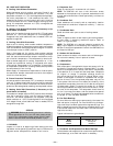
NOTE: For maximum benefit of outdoor air, set the enthalpy
control to the ‘‘A’’ setting. At this setting, when the relative
humidity is 50% and the outdoor air is below 74 F, the relay
contacts on the sensor will be closed.
9. Reinstall economizer hoods if removed.
IMPORTANT: Be sure all seal strips and RTV sealant are in-
tact. A watertight seal to inside of unit must be maintained.
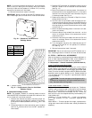
B. Differential Enthalpy Control
NOTE: The accessory outdoor-air enthalpy sensor must be
installed BEFORE the economizer hoods are installed on the
unit or hoods will have to be removed.
1. Remove and discard the factory-installed jumper as-
sembly containing the 800-ohm resistor on the econo-
mizer control module (between terminals S
R
and +. See
Fig. 15.
2. Disconnect black wire from economizer control module
terminal S
O
and blue wire from the OAT (outdoor-air
thermostat).
3. Remove OAT and black wire assembly containing the
620-ohm resistor from the outside of the economizer
(see Fig. 14).
4. Mount the outdoor-air enthalpy sensor (first sensor) to
the economizer on the outside of the unit (in the same
location from which the OAT was removed) using the
2 screws provided. See Fig. 14.
5. Reconnect the blue wire removed in Step 2 to the en-
thalpy sensor terminal +.
6. Cut the violet wire provided to desired length and ter-
minate with quick-connect terminal provided. Route the
violet wire from the enthalpy sensor terminal S, through
the snap bushing, and to the economizer control mod-
ule terminal S
O
.
7. Mount the second enthalpy sensor in the return-air duct
(return-air sensor).
8. Route the blue wire (provided) from terminal + on the
return-air enthalpy sensor to the economizer control
module terminal +.
9. Route the violet wire (provided) from terminal S on the
return-air enthalpy sensor to the economizer control
module terminal S
R
.
10. Turn changeover set point dial clockwise past the ‘‘D’’
setting, or the control will not operate on a differen-
tial. See Fig. 15.
11. Reinstall economizer hood if removed.
IMPORTANT: Be sure all seal strips and RTV sealant are in-
tact. A watertight seal to inside of unit must be maintained.
IX. STEP 9 — INSTALL ALL ACCESSORIES
After all the factory-installed options have been adjusted, in-
stall all field-installed accessories. Refer to the accessory in-
stallation instructions included with each accessory.
A. Motormasterா I Control Installation (559F180 and 216)
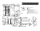
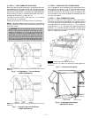
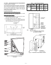
Install Field-Fabricated Wind Baffles
Wind baffles must be field-fabricated for all units to ensure
proper cooling cycle operation at low ambient temperatures.
See Fig. 22 for baffle details. Use 20-gage, galvanized sheet
metal, or similar corrosion-resistant metal for baffles. Use field-
supplied screws to attach baffles to unit. Screws should be
1
⁄
4
-in. diameter and
5
⁄
8
-in. long. Drill required screw holes for
mounting baffles.
CAUTION:
To avoid damage to the refrigerant coils
and electrical components, use recommended screw sizes
only. Use care when drilling holes.
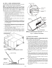
Install Motormaster I Controls
Only one Motormaster I control is required per unit. The Motor-
master I control must be used in conjunction with the Acces-
sory 0° F Low Ambient Kit (purchased separately). The
Motormaster I device controls outdoor fan no. 1 while out-
door fans no. 2 and 3 are sequenced off by the Accessory 0° F
Low Ambient Kit.
Accessory 0° F Low Ambient Kit — Install the Accessory
0° F Low Ambient Kit per instruction supplied with
accessory.
Motor Mount — To ensure proper fan height, replace the ex-
isting motor mount with the new motor mount provided with
accessory.
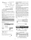
+
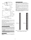
Fig. 20 — Outdoor-Air and Return-Air
Enthalpy Sensor
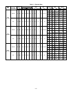
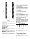
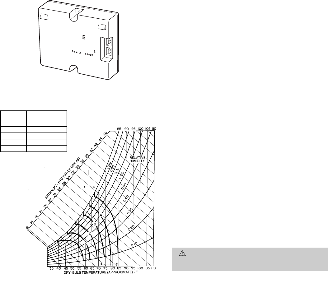
CONTROL
CURVE
CONTROL POINT
(Approx Deg)
AT 50% RH
A 73
B 68
C 63
D 58
RH — Relative Humidity
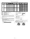
Fig. 21 — Psychrometric Chart for Solid-State
Enthalpy Control
—13—