


Crankcase Heater
Only the 559F300 unit is equipped with a 70-watt crankcase
heater to prevent absorption of liquid refrigerant by oil in the
crankcase when the compressor is idle. The crankcase heater
is energized whenever there is a main power to the unit and
the compressor is not energized.
IMPORTANT: After prolonged shutdown or servicing, ener-
gize the crankcase heaters for 24 hours before starting the
compressors.
Compressor Lockout
If any of the safeties (high-pressure, low-pressure, freeze pro-
tection thermostat, compressor internal thermostat) trip, or
if there is loss of power to the compressors, the CLO (com-
pressor lockout) will lock the compressors off. To reset, manu-
ally move the thermostat setting.
B. Evaporator Fan Motor Protection
A manual reset, calibrated trip, magnetic circuit breaker pro-
tects against overcurrent. Do not bypass connections or in-
crease the size of the breaker to correct trouble. Determine
the cause and correct it before resetting the breaker.
C. Condenser-Fan Motor Protection
Each condenser-fan motor is internally protected against
overtemperature.
D. High- and Low-Pressure Switches
If either switch trips, or if the compressor overtemperature
switch activates, that refrigerant circuit will be automati-
cally locked out by the CLO. To reset, manually move the ther-
mostat setting.
E. Freeze Protection Thermostat
An FPT is located on the top and bottom of the evaporator
coil. It detects frost build-up and turns off the compressor, al-
lowing the coil to clear. Once the frost has melted, the com-
pressor can be reenergized by resetting the compressor
lockout.
XII. RELIEF DEVICES
All units have relief devices to protect against damage from
excessive pressures (e.g., fire). These devices protect the high
and low side.
XIII. CONTROL CIRCUIT, 24-V
This control circuit is protected against overcurrent by a
3.2-amp circuit breaker. Breaker can be reset. If it trips, de-
termine cause of trouble before resetting.
XIV. REPLACEMENT PARTS
A complete list of replacement parts may be obtained from
any Carrier distributor upon request.
50
40
100
150
200
250
300
350
400
60
80
100
120
140
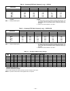
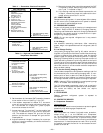
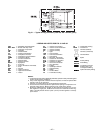
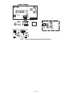
ALL OUTDOOR FANS MUST BE OPERATING
LIQUID PRESSURE AT LIQUID VALVE (PSIG)
LIQUID TEMPERATURE AT LIQUID VALVE (DEG F)
BOTH CIRCUITS
REDUCE CHARGE IF BELOW CURVE
ADD CHARGE IF ABOVE CURVE
Fig. 30 — Cooling Charging Chart — All Units
—24—