


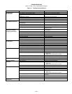


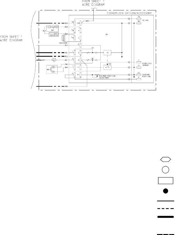
LEGEND AND NOTES FOR FIG. 31 AND 32
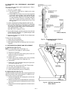
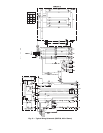
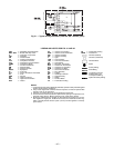
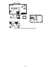
Fig. 31 — Typical Wiring Schematic (559F180, 460-v Shown) (cont)
AHA — Adjustable Heat Anticipator
BKR W/AT — Breaks with Amp Turns
C—Contactor, Compressor
CAP — Capacitor
CB — Circuit Breaker
CC — Cooling Compensator
CLO — Compressor Lockout
CLS — Compressor Lockout Switch
COMP — Compressor Motor
CT — Current Transformer
DM — Damper Motor
DU — Dummy Terminal
EQUIP — Equipment
FL — Fuse Link
FPT — Freeze Protection Thermostat
FU — Fuse
GND — Ground
HC — Heater Contactor
HPS — High-Pressure Switch
HTR — Heater
IFC — Indoor-Fan Contactor
IFCB — Indoor-Fan Circuit Breaker
IFM — Indoor-Fan Motor
IFR — Indoor-Fan Relay
L—Light
LOR — Lockout Relay
LPS — Low-Pressure Switch
LS — Limit Switch
MAT — Mixed-Air Thermostat
OAT — Outdoor-Air Thermostat
OFC — Outdoor-Fan Contactor
OFM — Outdoor-Fan Motor
OP — Overcurrent Protector
PL — Plug Assembly
PRI — Primary
QT — Quadruple Terminal
SR — Solenoid Relay
SW — Switch
TB — Terminal Block
TC — Thermostat Cooling
TH — Thermostat Heating
TRAN — Transformer
Terminal (Marked)
Terminal (Unmarked)
Terminal Block
Splice
Factory Wiring
Field Wiring
To Indicate Common
Potential Only, Not
To Represent Wiring
Option/Accessory Wiring
NOTES:
1. Compressor and fan motors thermally protected; 3-phase motors protected against
primary single-phasing conditions.
2. If any of the original wire furnished must be replaced, it must be replaced with
type 90 C wire or its equivalent.
3. Jumpers are omitted when unit is equipped with economizer.
4. The CLO locks out the compressor to prevent short cycling on compressor over-
load and safety devices. Before replacing CLO, check these devices.
5. Number(s) indicates the line location of used contacts. A bracket over (2) num-
bers signifies a single-pole, double-throw contact. An underlined number sig-
nifies a normally-closed contact. A plain (no line) number signifies a normally-
open contact.
—27—