


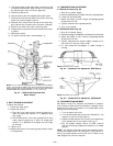

4. Using jacking bolt under motor base, raise motor to top
of slide and remove belt. Secure motor in this position
by tightening the nuts on the carriage bolts.
5. Remove the belt drive.
6. Remove jacking bolt and tapped jacking bolt plate.
7. Remove the 2 screws that secure the motor mounting
plate to the motor support channel.
8. Remove the 3 screws from the end of the motor sup-
port channel that interfere with the motor slide path.
9. Slide out the motor and motor mounting plate.
10. Disconnect wiring connections and remove the 4 mount-
ing bolts.
11. Remove the motor.
12. To install the new motor, reverse Steps 1-11.
V. BELT TENSION ADJUSTMENT
To adjust belt tension:
1. Loosen fan motor bolts.
2. Adjust belt tension:
a. Size 180 Units: Move motor mounting plate up or
down for proper belt tension (
1
⁄
2
in. deflection with
one finger).
b. Size 216-300 Units: Turn motor jacking bolt to move
motor mounting plate up or down for proper belt
tension (
3
⁄
8
in. deflection at midspan with one finger
[9 lb force]).
3. Tighten nuts.
4. Adjust bolts and nut on mounting plate to secure motor
in fixed position.
VI. CONDENSER-FAN ADJUSTMENT
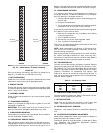
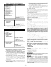
A. 559F180-216 Units (Fig. 28)
1. Shut off unit power supply.
2. Remove access panel(s) closest to the fan to be adjusted.
3. Loosen fan hub setscrews.
4. Adjust fan height on shaft using a straightedge placed
across the fan orifice.
5. Tighten setscrews and replace panel(s).
6. Turn on unit power.
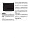
B. 559F240,300 Units (Fig. 29)
1. Shut off unit power supply.
2. Remove fan top-grille assembly and loosen fan hub screws.
3. Adjust fan height on unit, using a straightedge placed
across the fan orifice.
4. Tighten setscrews and replace rubber hubcap to pre-
vent hub from rusting to motor shaft.
5. Fill hub recess with permagum if rubber hubcap is
missing.
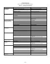
VII. ECONOMIZER ADJUSTMENT
See Tables 11 and 12 for checkout and outdoor-air tempera-
ture simulation. Make certain the outdoor-air damper is fully
closed and the return-air damper is fully open before com-
pleting the following steps.
1. Turn on power to the unit.
2. Turn the thermostat fan switch to the ON position. The
damper will go to the vent position.
3. Adjust the vent position with the minimum damper po-
sition adjustment on the module. See Fig. 15.
4. Set the system selector switch to COOL position
and set the cooling temperature selector to its lowest
setting.
NOTE: The Cooling mode may also be simulated by remov-
ing the thermostat wires from terminals Y1 and Y2 and in-
stalling a jumper between terminals R and Y1. Refer to unit
label diagram for terminal locations.
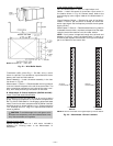
NOTE: A2
1
⁄
2
-in. bolt and threaded plate are included in the installer’s
packet. They should be added to the motor support channel below the
motor mounting plate to aid in raising the motor. The plate part number
is 50DP503842. The adjustment bolt is
3
⁄
8
-16x1
3
⁄
4
-in. LG.
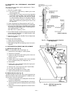
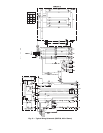
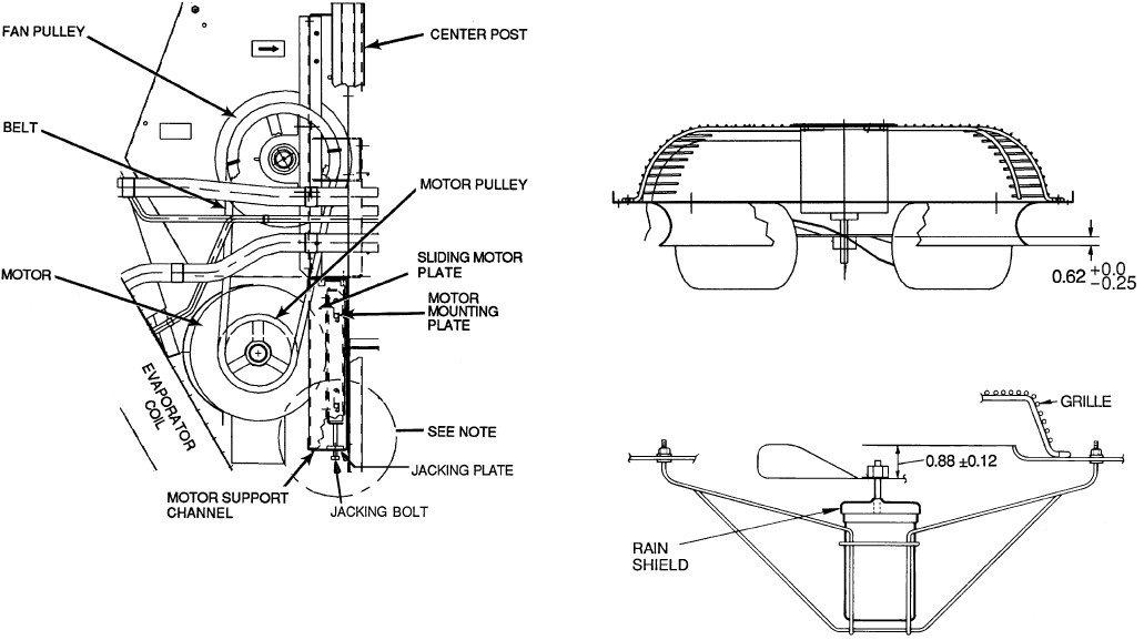
Fig. 27 — 559F216-300 Evaporator-Fan
Motor Section
NOTE: Dimensions are in inches.
Fig. 28 — Condenser Fan Adjustment, 559F180,216
NOTE: Dimensions are in inches.
Fig. 29 — Condenser-Fan Adjustment, 559F240,300
—22—