


Transformer (460-v Units Only) — On 460-v units, a trans-
former is required. The transformer is provided with the ac-
cessory and must be field-installed.
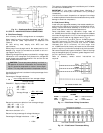
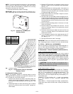
Sensor Assembly — Install the sensor assembly in the loca-
tion shown in Fig. 23.
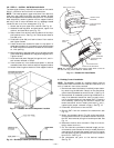
Motormaster I Control — Recommended mounting location
is on the inside of the panel to the left of the control box. The
control should be mounted on the inside of the panel, verti-
cally, with leads protruding from bottom of extrusion.
B. Motormaster III Control Installation (559F240 and 300)
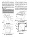
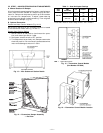
Install Field-Fabricated Wind Baffles
Wind baffles must be field-fabricated for all units to ensure
proper cooling cycle operation at low ambient temperatures.
See Fig. 22 for baffle details. Use 20-gage, galvanized sheet
metal, or similar corrosion-resistant metal for baffles. Use field-
supplied screws to attach baffles to unit. Screws should be
1
⁄
4
-in. diameter and
5
⁄
8
-in. long. Drill required screw holes for
mounting baffles.
CAUTION:
To avoid damage to the refrigerant coils
and electrical components, use recommended screw sizes
only. Use care when drilling holes.
Replace Outdoor Motor
Replace outdoor fan motor no. 1 with motor included in
accessory kit. Existing motor is not Motormaster III
compatible.
Install Motormaster III Controls
Only one Motormaster III control is required per unit.
Sensor — Install the sensor for thermistor input control in
the location shown in Fig. 24. Connect sensor leads to the
purple and grey control signal leads on the Motormaster III
control.
Signal Selection Switch — Remove the cover of the Motor-
master III control. Set the switch to accept the thermistor
sensor input signal. Set the frequency to match the unit power
supply (60 Hz).
Motormaster III Control — Recommended mounting location
is beneath the control box, mounted to the partition that sepa-
rates the control box section from the indoor section.
NOTE: If unit power is supplied through the roof curb and
basepan of the unit, mount the Motormaster III control on
the corner post adjacent to the conduit running from the base-
pan to the bottom of the control box.
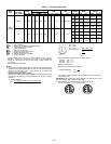
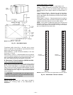
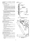
NOTE: Dimensions in ( ) are in mm.
Fig. 22 — Wind Baffle Details
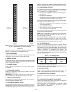
SENSOR
LOCATION
HAIRPIN END
SENSOR
LOCATION
HAIRPIN END
559F180 559F216
NOTE: All sensors are located on the eighth hairpin up from the bottom.
Fig. 23 — Motormaster I Sensor Locations
—14—