


START-UP
Use the following information and Start-Up Checklist on
page CL-1 to check out unit PRIOR to start-up.
I. UNIT PREPARATION
Check that unit has been installed in accordance with these
installation instructions and all applicable codes.
II. SERVICE VALVES
Ensure that optional suction, discharge, and standard liquid
line service valves are open. Damage to the compressor could
result if they are left closed.
III. INTERNAL WIRING
Check all electrical connections in unit control boxes; tighten
as required.
IV. CRANKCASE HEATER(S)
Heater(s) is energized as long as there is power to unit and
compressor is operating.
IMPORTANT: Unit power must be on for 24 hours prior to
start-up. Otherwise, damage to compressor may result.
V. COMPRESSOR MOUNTING
Compressors are internally spring mounted. Do not loosen or
remove compressor holddown bolts.
VI. REFRIGERANT SERVICE PORTS
Each refrigerant system has a total of 3 Schrader-type serv-
ice gage ports. One port is located on the suction line, one on
the compressor discharge line, and one on the liquid line. In
addition, Schrader-type valves are located underneath the low-
pressure switches. Be sure that caps on the ports are tight.
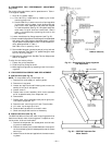
VII. COMPRESSOR ROTATION
It is important to be certain the compressors are rotating in
the proper direction. To determine whether or not compres-
sors are rotating in the proper direction:
1. Connect service gages to suction and discharge pres-
sure fittings.
2. Energize the compressor.
3. The suction pressure should drop and the discharge pres-
sure should rise, as is normal on any start-up.
If the suction pressure does not drop and the discharge pres-
sure does not rise to normal levels:
1. Note that the evaporator fan is probably also rotating
in the wrong direction.
2. Turn off power to the unit.
3. Reverse any two of the incoming power leads.
4. Turn on power to the compressor.
The suction and discharge pressure levels should now move
to their normal start-up levels.
NOTE: When compressors are rotating in the wrong direc-
tion, the unit will have increased noise levels and will not
provide heating and cooling.
After a few minutes of reverse operation, the scroll compres-
sor internal overload protection will open, which will acti-
vate the unit’s lockout and requires a manual reset. Reset is
accomplished by turning the thermostat on and off.
VIII. EVAPORATOR FAN
Fan belt and variable pulleys are factory installed. Remove
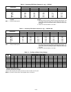
tape from the fan pulley. See Table 4 for Air Quantity Limits.
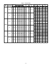
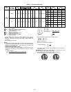
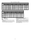
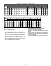
See Tables 5-7 for Fan Performance data. Be sure that fans
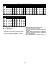
rotate in the proper direction. See Tables 8 and 9 for Static
Pressure information for accessories and options. See
Table 10 for fan rpm at various fan motor pulley settings. To
alter fan performance, see Evaporator-Fan Performance Ad-
justment section, page 21.
Table 4 — Air Quantity Limits
UNIT 559F MINIMUM CFM MAXIMUM CFM
180 4500 7,500
216 5400 9,000
240 6000 10,000
300 7000 11,250
IX. CONDENSER FANS AND MOTORS
Fans and motors are factory set. Refer to Condenser-Fan Ad-
justment section (page 22) as required.
X. RETURN-AIR FANS
Check that correct filters are installed in filter tracks. See
Table 1. Do not operate unit without return-air filters.
XI. OUTDOOR-AIR INLET SCREENS
Outdoor-air inlet screens must be in place before operating
unit.
XII. ACCESSORY ECONOMIZER ADJUSTMENT
Remove filter access panel. Check that outdoor-air damper is
closed and return-air damper is open.
Economizer operation and adjustment is described in Base
Unit Operation and Economizer Adjustment sections
(pages 20 and 22), respectively.
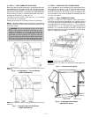
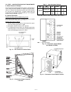
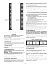
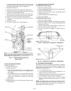
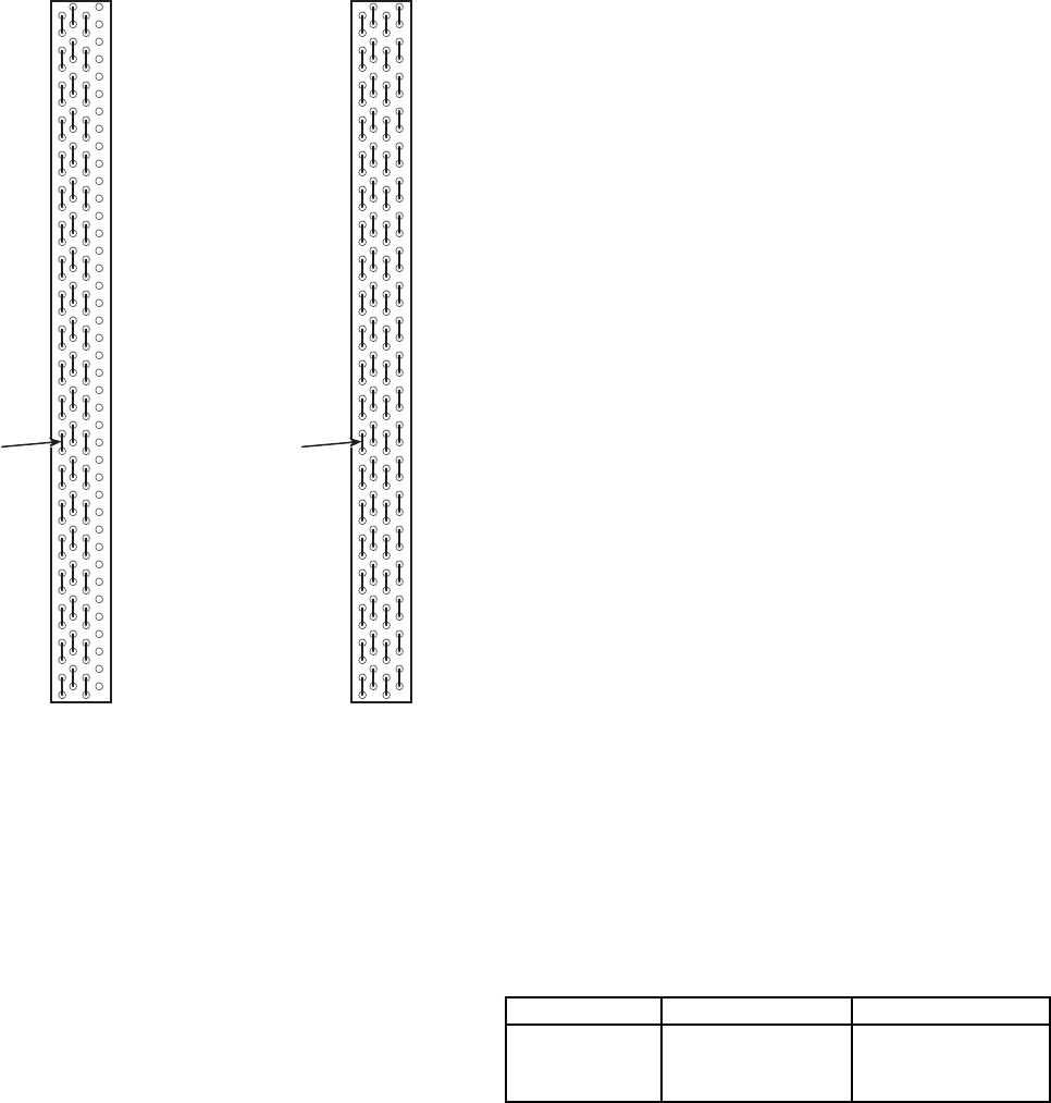
SENSOR
LOCATION
HAIRPIN END
SENSOR
LOCATION
HAIRPIN END
559F240 559F300
NOTE: All sensors are located on the eighth hairpin up from the bottom.
Fig. 24 — Motormasterா III Sensor Locations
—15—