


XIII. BASE UNIT OPERATION
A. Cooling, Units Without Economizer
When thermostat calls for cooling, terminals G and Y1 are
energized. The indoor (evaporator) fan contactor (IFC), and
compressor contactor no. 1 (C1) are energized and evaporator-
fan motor, compressor no. 1 and condenser fans start. The
condenser-fan motors run continuously while unit is cooling.
If the thermostat calls for a second stage of cooling by ener-
gizing Y2, compressor contactor no. 2 (C2) is energized and
compressor no. 2 starts.
B. Heating, Units Without Economizer (If Accessory or Op-
tional Heater is Installed)
Upon a call for heating through terminal W1, IFC and heater
contactor no. 1 (HC1) are energized. On units equipped for
2 stages of heat, when additional heat is needed, HC2 is en-
ergized through W2.
C. Cooling, Units With Economizer
Upon a call for cooling, when outdoor ambient temperature
is above the outdoor-air temperature control setting, the evapo-
rator and condenser fans and compressor energize. The econo-
mizer damper moves to VENT position.
Upon a first-stage call for cooling, when outdoor ambient
temperature is below the temperature control setting, the evapo-
rator fan starts and economizer damper modulates to main-
tain mixed-air temperature. The compressor(s) remains off.
Upon a second-stage call for cooling, compressor no. 1 is en-
ergized and mechanical cooling is integrated with econo-
mizer cooling. Compressor no. 2 is locked out. If the outdoor-
air temperature is below 50 F, a cooling lockout switch prevents
the compressor(s) from running.
When supply-air temperature drops below a fixed set point,
the economizer damper modulates to maintain the tempera-
ture at the fixed set point.
D. Freeze Protection Thermostat
A freeze protection thermostat (FPT) is located on the evapo-
rator coil. It detects frost build-up and turns off the compres-
sor, allowing the coil to clear. Once frost has melted, the com-
pressor can be reenergized by resetting the compressor lockout.
E. Heating, Units With Economizer (If Accessory or Op-
tional Heater Is Installed)
The outdoor air damper stays at VENT position while the evapo-
rator fan is operating. Upon a call for heating through ter-
minal W1, the indoor (evaporator) fan contactor (IFC) and
heater contactor no. 1 (HC1) are energized. On units equipped
for 2 stages of heat, when additional heat is needed, HC2 is
energized through W2.
SERVICE
WARNING:
Before performing service or mainte-
nance operations on unit, turn off main power switch
to unit. Turn off accessory heater power switch if appli-
cable. Electrical shock could cause personal injury.
I. CLEANING
Inspect unit interior at beginning of each heating and cool-
ing season and as operating conditions require. Remove unit
top panel and/or side panels for access to unit interior.
A. Evaporator Coil
Clean as required with a commercial coil cleaner.
NOTE: The 559F300 unit has a mist eliminator screen
attached to the evaporator coil to prevent condensate runoff
at high wet-bulb conditions. Check periodically and clean as
necessary.
B. Condenser Coil
Clean condenser coil annually and as required by location
and outdoor-air conditions. Inspect coil monthly — clean as
required.
C. Condensate Drain
Check and clean each year at start of cooling season.
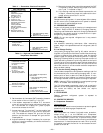
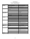
D. Filters
Clean or replace at start of each heating and cooling season,
or more often if operating conditions require. Refer to
Table 1 for type and size.
NOTE: The 559F300 unit requires industrial grade throw-
away filters capable of withstanding face velocities up to
625 fpm. Ensure that replacement filters for the 559F300 units
are rated for 625 fpm.
E. Outdoor-Air Inlet Screens
Clean screens with steam or hot water and a mild detergent.
Do not use throwaway filters in place of screens.
II. LUBRICATION
A. Compressors
Each compressor is charged with the correct amount of oil at
the factory. Conventional white oil (Sontext 200LT) is used.
White oil is compatible with 3GS oil, and 3GS oil may be used
if the addition of oil is required. See compressor nameplate
for original oil charge. A complete recharge should be
four ounces less than the original oil charge. When a com-
pressor is exchanged in the field it is possible that a major
portion of the oil from the replaced compressor may still be
in the system. While this will not affect the reliability of the
replacement compressor, the extra oil will add rotor drag and
increase power usage. To remove this excess oil, an access
valve may be added to the lower portion of the suction line at
the inlet of the compressor. The compressor should then be
run for 10 minutes, shut down, and the access valve opened
until no oil flows. This should be repeated twice to make sure
the proper oil level has been achieved.
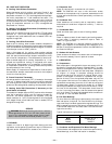
B. Fan Shaft Bearings
For size 180 units, bearings are permanently lubricated. No
field lubrication is required. For size 216-300 units, the bear-
ings are of the pillow block type and have grease fittings. The
bearing opposite the motor end has an extended tube line so
it can be lubricated from the motor side. Lubricate the bear-
ings twice annually.
Typical lubricants are given below:
MANUFACTURER LUBRICANT
Texaco Regal AFB-2*
Mobil Mobilplex EP No. 1
Sunoco Prestige 42
Texaco Multifak 2
*Preferred lubricant because it contains rust and oxidation inhibitors.
C. Condenser and Evaporator-Fan Motor Bearings
The condenser and evaporator-fan motors have permanently-
sealed bearings, so no field lubrication is necessary.
—20—