155
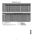
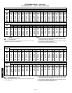
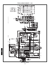
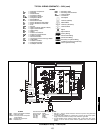
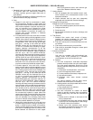
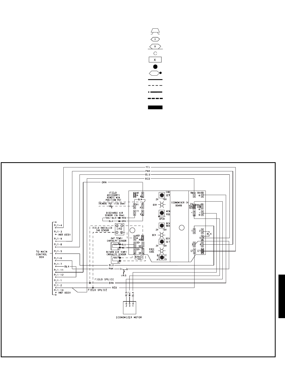
TYPICAL WIRING SCHEMATIC — 542J (cont)
LEGEND
C—Contactor, Compressor
CAP — Capacitor
CB — Circuit Breaker
CH — Crankcase Heater
CLO — Compressor Lockout
COMP — Compressor Motor
DB — Defrost Board
DFT — Defrost Thermostat
FL — Freeze Protection Limit Switch
FPT — Freeze Protection Thermostat
FU — Fuse
GND — Ground
HC — Heater Contactor (Electric Heater)
HPS — High-Pressure Switch
HR — Heater Relay
HTR — Heater
IFC — Indoor-Fan Contactor
IFCB — Indoor Fan Circuit Breaker
IFM — Indoor-Fan Motor
IP — Internal Protection
LPS — Low-Pressure/Loss-of-Charge Switch
LS — Limit Switch
OFM — Outdoor Fan Motor
OP — Overload Protection
QT — Quadruple Terminal
RVR — Reversing Valve
RVS — Reversing Valve Solenoid
TB — Terminal Block
TRAN — Transformer
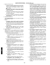
Field Splice
Terminal (Marked)
Marked Wire
Terminal (Unmarked)
Terminal Block
Splice
Splice Marked
Factory Wiring
Field Control Wiring
Field Power Wiring
Accessory or Optional Wiring
To indicate common potential only.
Not to represent wiring.
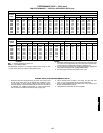
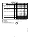
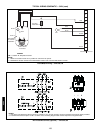
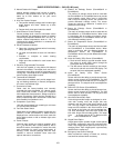
LEGEND
DCV — Demand Controlled Ventilation
IAQ — Indoor Air Quality
LALS— Low Temperature Compressor
Lockout Switch
OAT — Outdoor-Air Temperature
POT — Potentiometer
Potentiometer Defaults Settings:
Power Exhaust Middle
Minimum Pos. Fully Closed
DCV Max. Middle
DCV Set Middle
Enthalpy C Setting
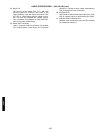
NOTES:
1. 620 ohm, 1 watt 5% resistor should be removed only when using differential
enthalpy or dry bulb.
2. If a separate field-supplied 24 v transformer is used for the IAQ sensor power
supply, it cannot have the secondary of the transformer grounded.
3. For field-installed remote minimum position POT, remove black wire jumper
between P and P1 and set control minimum position POT to the minimum
position.
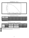
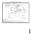
EconoMi$erIV Wiring — 542J150,180
a48-7992
542J


