


a. Remove factory-installed cap and clamp from LOWER
inducer housing drain connection.
b. Remove and discard UPPER (molded) inducer housing
drain tube which was previously connected to conden-
sate trap.
c. Install cap and clamp on UPPER inducer housing drain
connection where molded drain tube was removed.
d. Use inducer housing drain tube (violet label and factory-
supplied in loose parts bag) to connect LOWER inducer
housing drain connection to the condensate trap.
e. Connect inducer housing drain connection to condensate
trap.
(1.) Condensate Trap Located on Left Side of Casing
(a.) Determine appropriate length and cut.
(b.) Connect tube to condensate trap.
(c.) Clamp tube to prevent any condensate leakage.
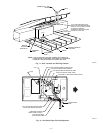
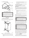
(2.) Condensate Trap Located on Right Side of Casing
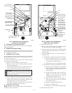
(a.) Route inducer housing drain tube (violet label)
directly from inducer housing to condensate
trap as shown in Fig. 9.
(b.) Determine appropriate length and cut.
(c.) Connect tube to condensate trap.
(d.) Clamp tube to prevent any condensate leakage.
3. Relief Port Tube
Refer to Pressure Switch Tubing section for connection
procedure.
C. Condensate Trap Field Drain Attachment
Refer to Condensate Drain section for recommendations and
procedures.
D. Pressure Switch Tubing
One collector box pressure tube (pink label) is factory connected to
the pressure switch for use when furnace is installed in UPFLOW
applications. This tube MUST be disconnected and used for the
condensate trap relief port tube. The other collector box pressure
tube (green label) which was factory connected to the condensate
trap relief port connection MUST be connected to the pressure
switch in DOWNFLOW or HORIZONTAL RIGHT applications.
NOTE: See Fig. 8 or 9 or tube routing label on main furnace door
to check for proper connections.
Relocate tubes as described below.
1. Disconnect collector box pressure tube (pink label) attached
to pressure switch.
2. Extend collector box pressure tube (green label) which was
previously connected to condensate trap relief port connec-
tion by splicing to small diameter tube (factory-supplied in
loose parts bag).
3. Connect collector box pressure tube (green label) to pres-
sure switch connection labeled COLLECTOR BOX.
4. Extend collector box pressure tube (pink label) which was
previously connected to pressure switch by splicing to
remaining small diameter tube (factory-supplied in loose
parts bag).
5. Route this extended tube (pink label) to condensate trap
relief port connection.
6. Determine appropriate length, cut, and connect tube.
7. Clamp tube to relief port connection.
E. Condensate Trap Freeze Protection
Refer to Condensate Drain Protection section for recommenda-
tions and procedures.
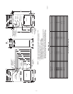
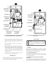
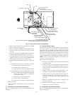
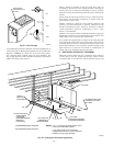
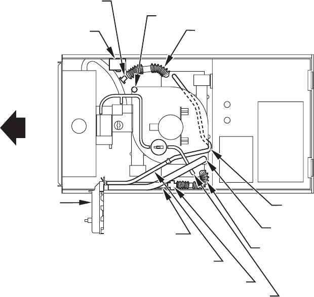
Fig. 10—Horizontal Left Tube Configuration
A00215
CONDENSATE
TRAP
AUXILIARY "J" BOX
PLUG
CAP
INDUCER HOUSING
DRAIN TUBE (VIOLET)
COLLECTOR BOX
DRAIN TUBE (BLUE)
COLLECTOR BOX TUBE (PINK)
RELOCATE TUBE BETWEEN BLOWER SHELF AND INDUCER HOUSING FOR
040, 060, AND 080 HEATING INPUT FURNACES
COLLECTOR BOX
EXTENSION TUBE
COLLECTOR BOX
DRAIN TUBE
(BLUE AND WHITE STRIPED)
DRAIN TUBE COUPLING
COLLECTOR BOX
TUBE (GREEN)
COLLECTOR
BOX EXTENSION
DRAIN TUBE
—9—