


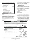
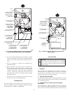
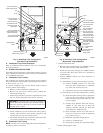
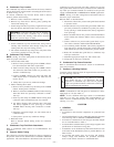
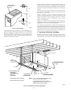
A. Condensate Trap Location
The condensate trap must be removed from the factory-installed
blower shelf location and relocated in selected application location
as shown in Fig. 2 or 12.
To relocate condensate trap from the blower shelf to desired
location, perform the following:
1. Remove 3 tubes connected to condensate trap.
2. Remove trap from blower shelf by gently pushing tabs
inward and rotating trap.
3. Install casing hole filler cap (factory-supplied in loose parts
bag) into blower shelf hole where trap was removed.
WARNING: Casing hole filler cap must be installed in
blower shelf hole when condensate trap is relocated.
Failure to follow this warning could result in electrical
shock, fire, personal injury or death.
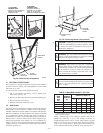
4. Install condensate trap into left-hand side casing hole by
inserting tube connection stubs through casing hole and
rotating until tabs snap into locking position.
5. Fill unused condensate trap casing holes with plastic filler
caps (factory-supplied in loose parts bag).
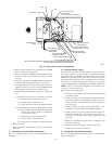
B. Condensate Trap Tubing
NOTE: See Fig. 12 or tube routing label on main furnace door to
check for proper connections.
1. Collector Box Drain Tube
a. Remove factory-installed plug from LOWER collector
box drain tube (blue and white striped label).
b. Install removed clamp and plug into UPPER collector
box drain tube (blue label) which was previously con-
nected to condensate trap.
c. Connect LOWER collector box drain tube (blue and
white striped label) to condensate trap. Tube does not
need to be cut.
d. Clamp tube to prevent any condensate leakage.
2. Inducer Housing Drain Tube
a. Remove factory-installed cap and clamp from LOWER
inducer housing drain connection.
b. Remove and discard UPPER (molded) inducer housing
drain tube which was previously connected to conden-
sate trap.
c. Install cap and clamp on UPPER inducer housing drain
connection where molded drain tube was removed.
d. Use inducer housing drain extension tube (violet label
and factory-supplied in loose parts bag) to connect
LOWER inducer housing drain connection to conden-
sate trap.
e. Determine appropriate length, cut, and connect tube to
condensate trap.
f. Clamp tube to prevent any condensate leakage.
3. Relief Port Tube
Refer to Pressure Switch Tubing section for connection
procedure.
C. Condensate Trap Field Drain Attachment
Refer to Condensate Drain section for recommendations and
procedures.
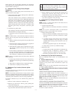
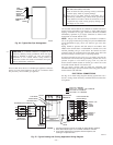
D. Pressure Switch Tubing
One collector box pressure tube (pink label) is factory connected to
the pressure switch for use when furnace is installed in UPFLOW
applications. This tube MUST be disconnected and used for the
condensate trap relief port tube. The other collector box pressure
tube (green label) which was factory connected to the condensate
trap relief port connection MUST be connected to the pressure
switch in DOWNFLOW or HORIZONTAL RIGHT applications.
NOTE: See Fig. 12 or tube routing label on main furnace door to
check for proper connections.
Relocate tubes as described below.
1. Disconnect collector box pressure tube (pink label) attached
to pressure switch.
2. Extend collector box pressure tube (green label) which was
previously connected to condensate trap relief port connec-
tion by splicing to small diameter tube (factory-supplied in
loose parts bag).
3. Route extended collector box pressure tube behind inducer
motor bracket then between inducer motor and pressure
switch.
4. Connect collector box pressure tube (green label) to pres-
sure switch connection labeled COLLECTOR BOX.
5. Use remaining smaller diameter tube (factory-supplied in
loose parts bag) to extend collector box pressure tube (pink
label) which was previously connected to pressure switch.
6. Route this extended tube (pink label) to condensate trap
relief port connection.
7. Determine appropriate length, cut, and connect tube.
8. Clamp tube to relief port connection.
E. Condensate Trap Freeze Protection
Refer to Condensate Drain Protection section for recommenda-
tions and procedures.
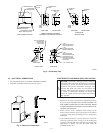
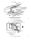
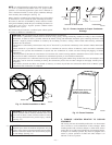
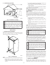
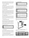
F. Construct a Working Platform
Construct working platform where all required furnace clearances
are met. (See Fig. 3 and 11.)
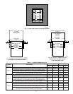
CAUTION: The condensate trap MUST be installed
below furnace. See Fig. 5 for dimensions. The drain
connection to condensate trap must also be properly
sloped to an open drain. Failure to follow this caution will
result in intermittent unit operation.
NOTE: Combustion-air and vent pipes are restricted to a mini-
mum length of 5 ft. (See Table 7.)
NOTE: A 12-in. minimum offset pipe section is recommended
with short (5 to 8 ft) vent systems. This recommendation is to
reduce excessive condensate droplets from exiting the vent pipe.
(See Fig. 11 or 34.)
LOCATION
I. GENERAL
This furnace must
• be installed so the electrical components are protected from
water.
• not be installed directly on any combustible material other than
wood flooring (refer to SAFETY CONSIDERATIONS).
• be located so combustion-air and vent pipe maximum lengths
are not exceeded. Refer to Table 7.
• be located where available electric power and gas supplies meet
specifications on the furnace rating plate.
• be attached to an air distribution system and be located as close
to the center of the distribution system as possible. Refer to Air
Ducts section.
• be provided with ample space for servicing and cleaning.
Always comply with minimum fire protection clearances
shown on the furnace clearance to combustible label.
—12—
→