


CAUTION: If a flexible connector is required or al-
lowed by authority having jurisdiction, black iron pipe
shall be installed at furnace gas valve and extend a
minimum of 2 in. outside furnace casing. Failure to
follow this caution will result in intermittent unit opera-
tion or performance satisfaction.
If local codes allow the use of a flexible gas appliance connector,
always use a new listed connector. Do not use a connector which
has previously served another gas appliance.
WARNING:
FIRE OR EXPLOSION HAZARD
Failure to follow the safety warnings exactly could result
in serious injury, death or property damage.
Never test for gas leaks with an open flame. Use a
commercially available soap solution made specifically
for the detection of leaks to check all connections. A fire
or explosion may result causing property damege, per-
sonal injury or loss of life.
An accessible manual shutoff valve MUST be installed external to
furnace casing and within 6 ft of furnace. A 1/8-in. NPT plugged
tapping, accessible for test gage connection, MUST be installed
immediately upstream of gas supply connection to furnace and
downstream of manual shutoff valve.
NOTE: The gas valve inlet pressure tap connection is suitable to
use as test gauge connection providing test pressure DOES NOT
exceed maximum 0.5 psig (14-in. wc) stated on gas valve. (See
Fig. 50.)
Piping should be pressure and leak tested in accordance with
NFGC in the United States or NSCNGPIC in Canada, local, and
national plumbing and gas codes before the furnace has been
connected. After all connections have been made, purge lines and
check for leakage at furnace prior to operating furnace.
If pressure exceeds 0.5 psig (14-in. wc), gas supply pipe must be
disconnected from furnace and capped before pressure test. If test
pressure is equal to or less than 0.5 psig (14-in. wc), turn off
electric shutoff switch located on furnace gas control valve and
accessible manual shutoff valve before test.
The gas supply pressure shall be within the maximum and
minimum inlet supply pressure marked on the rating plate with the
furnace burners ON and OFF.
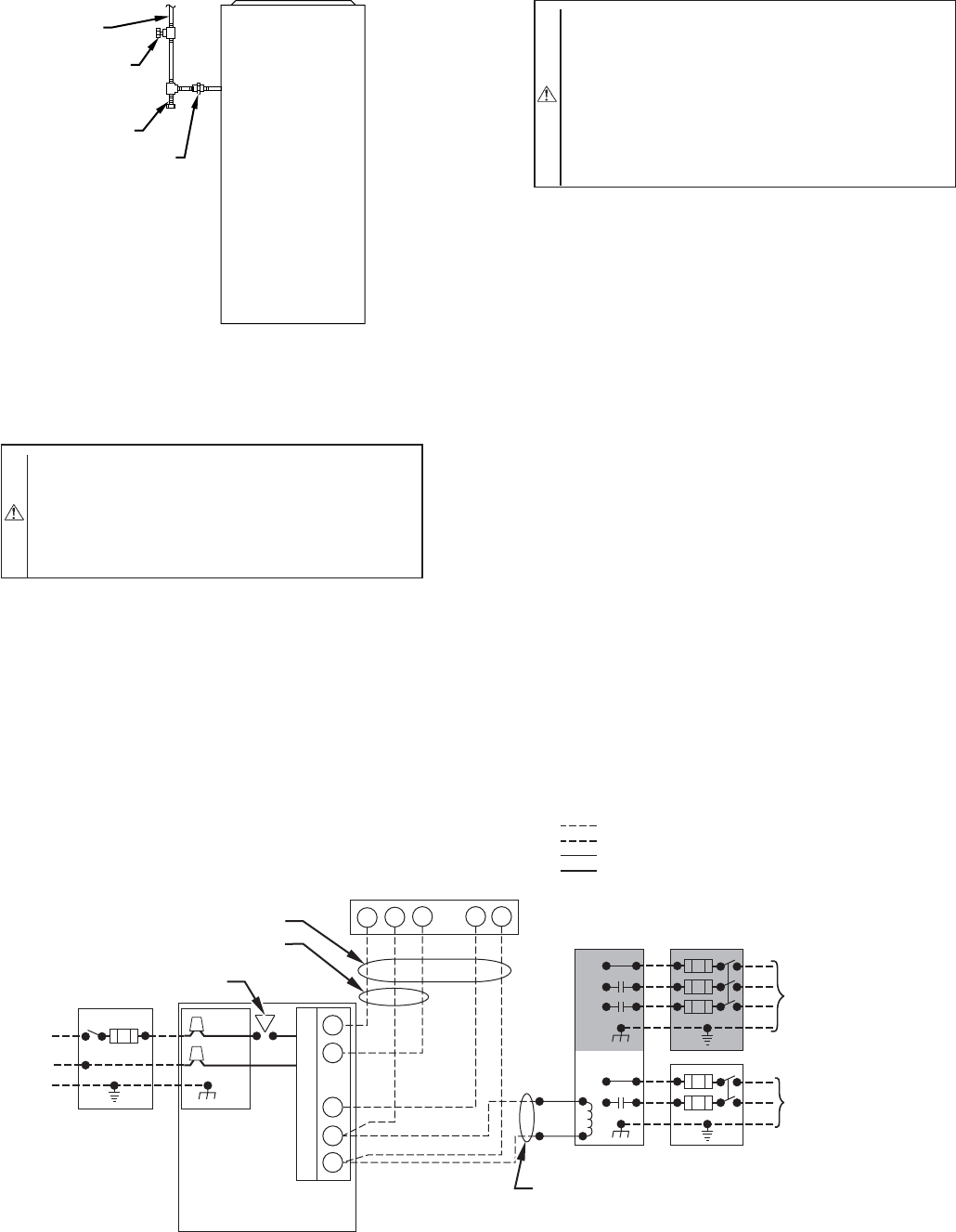
ELECTRICAL CONNECTIONS
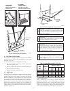
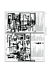
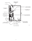
See Fig. 27 for field wiring diagram showing typical field 115-v
and 24-v wiring. Check all factory and field electrical connections
for tightness.
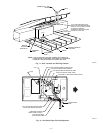
Fig. 27—Typical Heating and Cooling Application Wiring Diagram
A02174
115-V FIELD-
SUPPLIED
DISCONNECT
AUXILIARY
J-BOX
24-V
TERMINAL
BLOCK
THREE-WIRE
HEATING-ONLY
FIVE WIRE
NOTE 1
NOTE 2
FIELD-SUPPLIED
DISCONNECT
CONDENSING
UNIT
TWO
WIRE
FURNACE
C
O
N
T
R
O
L
R
G
COM
WCR GY
GND
GND
FIELD 24-V WIRING
FIELD 115-, 208/230-, 460-V WIRING
FACTORY 24-V WIRING
FACTORY 115-V WIRING
208/230- OR
460-V
THREE
PHASE
208/230-V
SINGLE
PHASE
BLOWER DOOR SWITCH
WHT
BLK
WHT
BLK
NOTES: Connect Y-terminal in furnace as shown for proper blower operation.
Some thermostats require a "C" terminal connection as shown.
If any of the original wire, as supplied, must be replaced, use
same type or equivalent wire.
W
Y
GND
THERMOSTAT
TERMINALS
1.
2.
3.
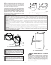
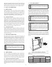
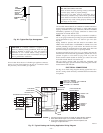
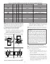
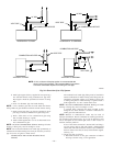
Fig. 26—Typical Gas Pipe Arrangement
A93324
UNION
SEDIMENT
TRAP
MANUAL
SHUTOFF
VALVE
(REQUIRED)
GAS
SUPPLY
—19—
→