


NOTE: DO NOT connect furnace control HUM terminal to HUM
(humidifier) terminal on Thermidistat™, Zone Controller or simi-
lar device. See Thermidistat™, Zone Controller, thermostat, or
controller manufacturer’s instructions for proper connection.
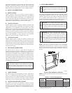
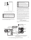
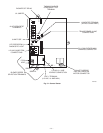
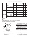
2. Humidifier (HUM)
A quick-connect terminal (HUM) and screw terminal (C
OM
24-v) are provided for 24-v humidifier connection. (See Fig.
30.) HUM terminal is energized with 24v (0.5-amp maxi-
mum) when gas valve is energized.
NOTE: A field-supplied, 115-v controlled relay connected to
EAC terminals may be added if humidifier operation is desired
during blower operation.
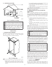
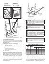
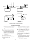
DIRECT VENTING
The 340MAV Furnaces require a dedicated (one 340MAV furnace
only) direct-vent system. In a direct-vent system, all air for
combustion is taken directly from outdoor atmosphere, and all flue
gases are discharged to outdoor atmosphere.
I. REMOVAL OF EXISTING FURNACES FROM
COMMON VENT SYSTEMS
When an existing Category I furnace is removed or replaced, the
original venting system may no longer be sized to properly vent
the remaining attached appliances. An improperly sized Category
I venting system could cause the formation of condensate in the
furnace and vent, leakage of condensate and combustion products,
spillage of combustion products into the living space, etc.
WARNING: CARBON MONOXIDE POISONING HAZARD
Failure to follow the steps outlined below for each appliance connected to the venting system being placed into operation could result
in carbon monoxide poisoning or death.
The following steps shall be followed for each appliance connected to the venting system being placed into operation, while all other
appliances connected to the venting system are not in operation:
1. Seal any unused openings in venting system.
2. Inspect the venting system for proper size and horizontal pitch, as required in the National Fuel Gas Code, ANSI Z223.1-2002/NFPA
54-2002 or the CSA B149.1, Natural Gas and Propane Installation Code and these instructions. Determine that there is no blockage
or restriction, leakage, corrosion and other deficiencies, which could cause an unsafe condition.
3. As far as practical, close all building doors and windows and all doors between the space in which the appliance(s) connected to the
venting system are located and other spaces of the building.
4. Close fireplace dampers.
5. Turn on clothes dryers and any appliance not connected to the venting system. Turn on any exhaust fans, such as range hoods and
bathroom exhausts, so they are operating at maximum speed. Do not operate a summer exhaust fan.
6. Follow the lighting instructions. Place the appliance being inspected into operation. Adjust the thermostat so appliance is operating
continuously.
7. Test for spillage from draft hood equipped appliances at the draft hood relief opening after 5 minutes of main burner operation. Use
the flame of a match or candle.
8. If improper venting is observed during any of the above tests, the venting system must be corrected in accordance with the National
Fuel Gas Code, ANSI Z223.1-2002/NFPA 54-2002 and/or CSA B149.1, Natural Gas and Propane Installation Code.
9. After it has been determined that each appliance connected to the venting system properly vents when tested as outlined above, return
doors, windows, exhaust fans, fireplace dampers and any other gas-fired appliance to their previous conditions of use.
Vent system or vent connectors may need to be resized. For any
other appliances when resizing vent systems or vent connectors,
system or connector must be sized to approach minimum size as
determined using appropriate table found in the NFGC or NSC-
NGPIC.
II. COMBUSTION-AIR AND VENT PIPING
A. General
Combustion-air and vent pipe, fittings, primers, and solvents must
conform to American National Standards Institute (ANSI) stan-
dards and American Society for Testing and Materials (ASTM)
standards. See Table 6 for approved materials for use in the U.S.A.
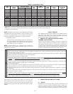
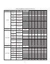
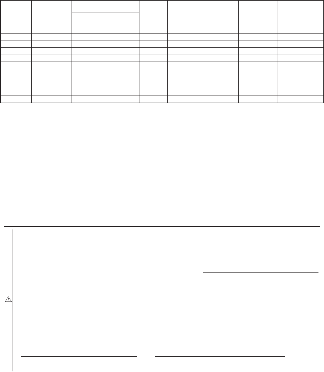
TABLE 4—ELECTRICAL DATA
UNIT
SIZE
VOLTS—
HERTZ—
PHASE
OPERATING
VOLTAGE RANGE
MAX
UNIT
AMPS
UNIT
AMPACITY†
MIN
WIRE
GAGE
MAX WIRE
LENGTH
(FT)‡
MAX FUSE
OR CKT BKR
AMPS**
Max* Min*
024040 115—60—1 127 104 6.1 8.4 14 44 15
036040 115—60—1 127 104 7.3 10.0 14 37 15
024060 115—60—1 127 104 6.1 8.4 14 44 15
036060 115—60—1 127 104 7.1 9.8 14 38 15
048060 115—60—1 127 104 9.5 12.8 14 29 15
036080 115—60—1 127 104 7.6 10.4 14 36 15
048080 115—60—1 127 104 10.0 13.4 14 28 15
060080 115—60—1 127 104 14.1 18.4 12 31 20
048100 115—60—1 127 104 10.2 13.5 14 27 15
060100 115—60—1 127 104 14.8 19.3 12 30 20
060120 115—60—1 127 104 14.6 19.1 12 30 20
060140 115—60—1 127 104 14.3 18.8 12 30 20
* Permissible limits of voltage range at which unit will operate satisfactorily.
† Unit ampacity = 125 percent of largest operating component’s full load amps plus 100 percent of all other potential operating components’ (EAC, humidifier, etc.) full load
amps.
‡ Length shown is as measured 1 way along wire path between unit and service panel for maximum 2 percent voltage drop.
** Time-delay type is recommended.
—22—