


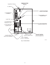
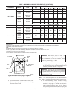
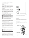

5. Check required dimensions as shown in Fig. 36, 39, or 40.
C. Concentric Vent/Air Termination Kit
1. Determine location for termination.
Consideration of the following should be made when
determining an appropriate location for termination kit.
a. Comply with all clearance requirements as stated in
Table 5.
b. Termination kit should be positioned where vent vapors
will not damage plants/shrubs or air conditioning equip-
ment.
c. Termination kit should be positioned so it will not be
affected by wind eddy (such as inside building corners)
or that may allow recirculation of flue gases, airborne
leaves, or light snow.
d. Termination kit should be positioned where it will not be
damaged by or subjected to foreign objects, such as
stones, balls, etc.
e. Termination kit should be positioned where vent vapors
are not objectionable.
2. Cut one 4-in. diameter hole for 2-in. kit, or one 5-in.
diameter hole for 3-in. kit.
3. Loosely assemble concentric vent/air termination compo-
nents together using instructions in kit.
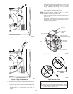
4. Slide assembled kit with rain shield REMOVED through
hole.
NOTE: Do not allow insulation or other materials to accumulate
inside of pipe assembly when installing it through hole.
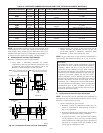
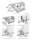
Roof terminations—Locate assembly through roof to ap-
propriate height as shown in Fig. 37.
Sidewall terminations—Locate assembly through sidewall
with rain shield positioned no more than 1-in. from wall as
shown in Fig. 38.
5. Disassemble loose pipe fittings. Clean and cement using
same procedures as used for system piping.
6. Check required dimensions as shown in Fig. 37 or 38.
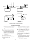
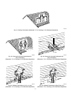
IV. MULTIVENTING AND VENT TERMINATIONS
When 2 or more 340MAV Furnaces are vented near each other,
each furnace must be individually vented. NEVER common vent
or breach vent 340MAV furnaces. When 2 or more 340MAV
furnaces are vented near each other, 2 vent terminations may be
installed as shown in Fig. 41, 42, 43, 44, and 45, but next vent
termination must be at least 36 in. away from first 2 terminations.
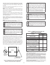
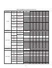
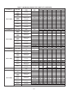
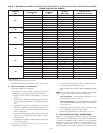
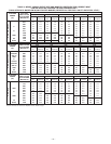
TABLE 8—MAXIMUM ALLOWABLE EXPOSED VENT PIPE LENGTH (FT) WITH AND WITHOUT INSULATION IN WINTER
DESIGN TEMPERATURE AMBIENT*
FURNACE
SIZE
WINTER DESIGN
TEMPERATURE
(°F)
MAX PIPE
DIAMETER
(IN.)
WITHOUT
INSULATION
WITH 3/8–IN. OR
THICKER INSULATION†
040
20 1.5 51 70
0 1.5 28 70
-20 1.5 16 70
20 2 45 70
0 2 22 70
-20 2 10 58
060
20 2 65 70
0 2 35 70
-20 2 20 70
080
20 2 55 55
0 2 48 55
-20 2 30 55
20 2.5 70 70
0 2.5 47 70
-20 2.5 28 70
100
20 2.5 40 40
0 2.5 40 40
-20 2.5 38 40
20 3 70 70
0 3 50 70
-20 3 28 70
120
20 3 70 70
0 3 61 70
-20 3 37 70
20 4 70 70
0 4 48 70
-20 4 23 70
140
20 3 60 60
0 3 60 60
-20 3 44 60
20 4 70 70
0 4 57 70
-20 4 30 70
* Pipe length (ft) specified for maximum pipe lengths located in unconditioned spaces. Pipes located in unconditioned space cannot exceed total allowable pipe length as
specified in Table 7.
† Insulation thickness based on R value of 3.5 per in.
—31—