


4. If you touch ungrounded objects (and recharge your body
with static electricity), firmly touch a clean, unpainted metal
surface of the furnace again before touching control or
wires.
5. Use this procedure for installed and uninstalled (un-
grounded) furnaces.
6. Before removing a new control from its container, dis-
charge your body’s electrostatic charge to ground to protect
the control from damage. If the control is to be installed in
a furnace, follow items 1 through 5 before bringing the
control or yourself into contact with the furnace. Put all
used AND new controls into containers before touching
ungrounded objects.
7. An ESD service kit (available from commercial sources)
may also be used to prevent ESD damage.
INTRODUCTION
The model 340MAV 4-way multipoise, Gas-Fired, Category IV,
direct-vent condensing furnace is available in model sizes ranging
in input capacities of 40,000 to 138,000 Btuh.
APPLICATIONS
CAUTION: Local codes may require a drain pan under
entire furnace and condensate trap when a condensing
furnace is used in an attic application or over a finished
ceiling. Failure to follow this caution will result in minor
property damage.
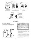
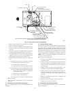
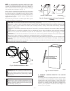
I. GENERAL
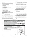
Some assembly and modifications are required for furnaces
installed in any of the 4 applications shown in Fig. 1. All drain and
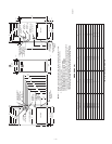
pressure tubes are connected as shown in Fig. 6. See appropriate
application instructions for these procedures.
II. UPFLOW APPLICATIONS
An upflow furnace application is where furnace blower is located
below combustion and controls section of furnace, and conditioned
air is discharged upwards.
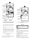
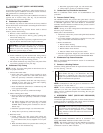
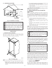
A. Condensate Trap Location (Factory-Shipped
Orientation)
The condensate trap is factory installed in the blower shelf and
factory connected for UPFLOW applications. A factory-supplied
tube is used to extend the condensate trap drain connection to the
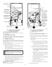
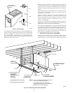
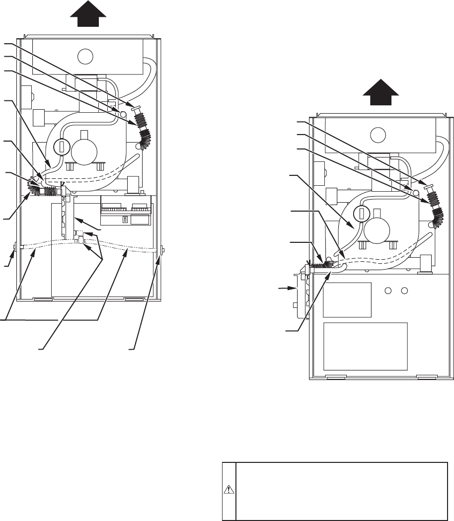
Fig. 6—Factory-Shipped Upflow Tube Configuration
(Shown With Blower Access Panel Removed)
A00288
COLLECTOR BOX
TUBE (PINK)
COLLECTOR BOX
TUBE (GREEN)
INDUCER HOUSING
(MOLDED) DRAIN
TUBE (BEHIND
COLLECTOR BOX
DRAIN TUBE)
COLLECTOR BOX
DRAIN TUBE (BLUE)
FIELD-INSTALLED
FACTORY-SUPPLIED
DRAIN TUBE
COUPLING (LEFT
DRAIN OPTION)
FIELD-INSTALLED
FACTORY-SUPPLIED
DRAIN TUBE
FIELD-INSTALLED
FACTORY-SUPPLIED
1
⁄2-IN. CPVC STREET
ELBOWS (2) FOR
LEFT DRAIN OPTION
FIELD-INSTALLED
FACTORY-SUPPLIED
DRAIN TUBE
COUPLING (RIGHT
DRAIN OPTION)
CAP
COLLECTOR BOX
DRAIN TUBE (BLUE
& WHITE STRIPED)
PLUG
CONDENSATE
TRAP
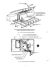
Fig. 7—Alternate Upflow Tube Configuration and
Trap Location
A00289
COLLECTOR BOX
TUBE (PINK)
CONDENSATE
TRAP
COLLECTOR BOX
TUBE (GREEN)
COLLECTOR BOX
DRAIN TUBE (BLUE)
INDUCER
HOUSING
DRAIN TUBE
(VIOLET)
CAP
COLLECTOR BOX
DRAIN TUBE (BLUE
& WHITE STRIPED)
PLUG
—6—
→