


Air Conditioning Contractors National Association (SMACNA) or
American Society of Heating, Refrigerating and Air Conditioning
Engineers (ASHRAE) or consult The Air Systems Design Guide-
lines reference tables available from your local distributor. The
duct system should be sized to handle the required system design
CFM at the design static pressure.
When a furnace is installed so that the supply ducts carry air
circulated by the furnace to areas outside the space containing the
furnace, the return air shall also be handled by a duct(s) sealed to
the furnace casing and terminating outside the space containing the
furnace.
Secure ductwork with proper fasteners for type of ductwork used.
Seal supply- and return-duct connections to furnace with code
approved tape or duct sealer.
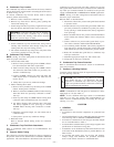
Flexible connections should be used between ductwork and
furnace to prevent transmission of vibration. Ductwork passing
through unconditioned space should be insulated to enhance
system performance. When air conditioning is used, a vapor
barrier is recommended.
Maintain a 1-in. clearance from combustible materials to supply air
ductwork for a distance of 36 in. horizontally from the furnace. See
NFPA 90B or local code for further requirements.
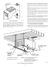
For a furnace not equipped with a cooling coil, the outlet duct shall
be provided with a removable access panel. This opening shall be
accessible when the furnace is installed and shall be of such a size
that the heat exchanger can be viewed for possible openings using
light assistance or a probe can be inserted for sampling the air
stream. The cover attachment shall prevent leaks.
II. DUCTWORK ACOUSTICAL TREATMENT
Metal duct systems that do not have a 90 degree elbow and 10 ft
of main duct to the first branch take-off may require internal
acoustical lining. As an alternative, fibrous ductwork may be used
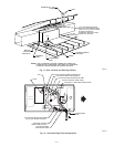
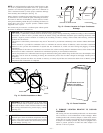
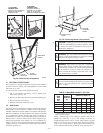
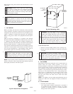
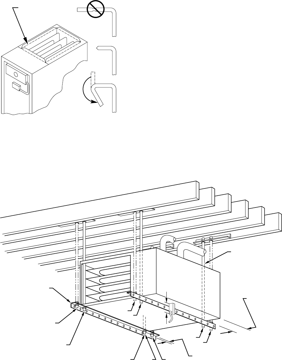
Fig. 21—Duct Flanges
A93029
NO
YES
YES
PERFORATED
DISCHARGE DUCT
FLANGE
210°
MIN
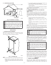
Fig. 22—Crawlspace Horizontal Application
A93304
NOTES:
ANGLE
IRON OR
EQUIVALENT
(B)
(A) ROD LOCATION
USING DIMPLE
LOCATORS
(SEE DIMENSIONAL
DWG FOR
LOCATIONS)
13
/16-IN. MAX
ALTERNATE SUPPORT
LOCATION FROM BACK
ALTERNATE SUPPORT
LOCATION 4-IN. MIN
8-IN. MAX
3
⁄8-IN. ROD
(A)
(B)
(A)
(B)
(B)
(A)
1. A 1 In. clearance minimum between top of
furnace and combustible material.
2. The entire length of furnace must be
supported when furnace is used in horizontal
position to ensure proper drainage.
(A) PREFERRED ROD LOCATION
(B) ALTERNATE ROD LOCATION
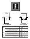
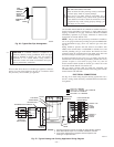
DRAIN
5
3
⁄
4
″
3
/8-IN. HEX NUT
& WASHER (4)
REQD PER ROD
—16—