


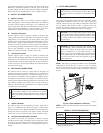
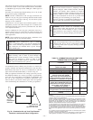
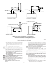
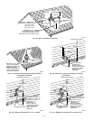
NOTE: The minimum combustion-air and vent pipe length (each)
for these furnaces is 5 ft. Short pipe lengths (5-8 ft) may discharge
water droplets. These droplets may be undesirable, and a 12-in.
minimum offset pipe section is recommended, as shown in Fig. 34,
to reduce excessive droplets from exiting vent pipe outlet.
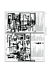
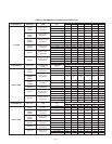
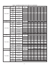
B. Combustion-Air and Vent Pipe Diameter
Determine combustion-air and vent pipe diameter.
1. Using Table 7, individually determine the smallest
combustion-air and vent pipe diameters permitted for each
pipe. Pick the larger of these 2 pipe diameters and use this
diameter for both combustion-air and vent pipes.
2. When installing vent systems of short pipe length, use the
smallest allowable pipe diameter. Do not use pipe size
greater than required or incomplete combustion, flame
disturbance, or flame sense lockout may occur.
NOTE: Do not count elbows or pipe sections in terminations or
within furnace. See shaded areas in Fig. 36, 37, 38, 39, and 40.
EXAMPLE:
An 036080 size furnace located in Indianapolis, elevation
650 ft above sea level, could be installed in an application
requiring 3 elbows and 32 ft of vent pipe, along with 5
elbows and 34 ft of combustion-air pipe. Table 7 indicates
this application would allow a 2-in. diameter vent pipe, but
require a 2-1/2 in. diameter combustion air pipe (2-in. pipe
is good for 35 ft with 3 elbows, but only 30 ft with 5
elbows). Therefore, 2-1/2 in. diameter pipe must be used
for both vent and combustion-air pipes since larger required
diameter must always be used for both pipes. If same
installation were in Albuquerque, elevation 5250 ft above
sea level, installation would require 2-1/2 in. vent pipe and
combustion-air pipe. At 5001- to 6000-ft elevation, 2-in.
pipe is only good for 17 ft with 5 elbows, and 2-1/2 in. pipe
is good for 70 ft with 5 elbows.
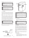
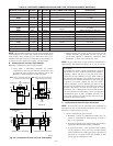
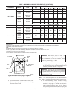
C. Combustion-Air and Vent Pipe Attachment
NOTE: All pipe joints must be cemented except attachment of
combustion-air pipe to inlet housing connection, since it may be
necessary to remove pipe for servicing.
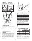
1. Attach combustion-air pipe as follows:
a. Determine location of combustion-air intake pipe con-
nection to combustion-air intake housing as shown in
Fig. 33 for application.
b. Reposition combustion-air intake housing plug fitting in
appropriate unused intake housing connection.
c. If required per Table 7, insert perforated disk assembly
(factory-supplied in loose parts bag) in intake housing
where combustion-air intake pipe will be connected. If
half disk set is required, install with shoulder of disk
against stop in combustion-air inlet.
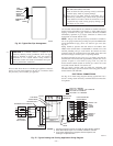
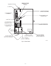
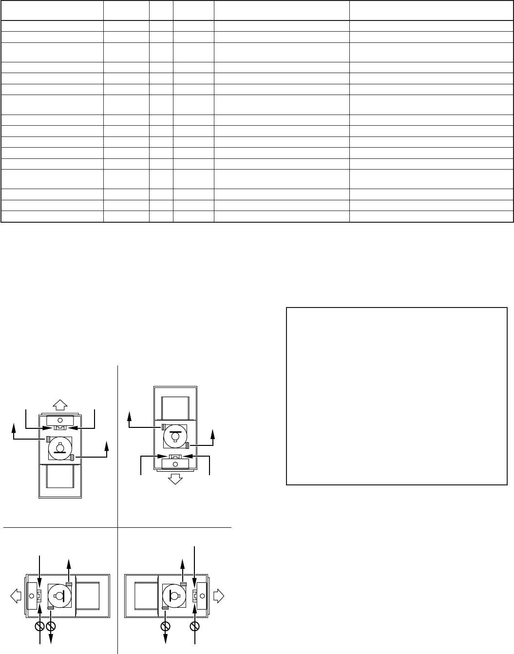
Fig. 33—Combustion-Air and Vent Pipe Connections
A96187
COMBUSTION-
AIR
COMBUSTION-
AIR
AIR
FLOW
VENT
VENT
VENT
AIR
FLOW
AIR
FLOW
AIR
FLOW
UPFLOW DOWNFLOW
HORIZONTAL-LEFT DISCHARGE HORIZONTAL-RIGHT DISCHARGE
Select 1 vent pipe connection and
1 combustion-air pipe connection.
COMBUSTION-
AIR
COMBUSTION-
AIR
COMBUSTION-
AIR
COMBUSTION-
AIR
VENT
VENT
VENT
NOTE: Select 1 vent pipe connection and
1 combustion-air pipe connection.
NOTE:
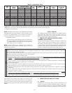
TABLE 6—APPROVED COMBUSTION-AIR AND VENT PIPE, FITTING AND CEMENT MATERIALS
ASTM SPECIFICATION
(MARKED ON MATERIAL)
MATERIAL PIPE FITTINGS SOLVENT CEMENT AND PRIMERS DESCRIPTION
D1527 ABS Pipe — — Schedule-40
D1785 PVC Pipe — — Schedule-40
D2235 For ABS — —
Solvent
Cement
For ABS
D2241 PVC Pipe — — SDR-21 & SDR-26
D2466 PVC — Fittings — Schedule-40
D2468 ABS — Fittings — Schedule-40
D2564 For PVC — —
Solvent
Cement
For PVC
D2661 ABS Pipe Fittings — DWV at Schedule-40 IPS sizes
D2665 PVC Pipe Fittings — DWV
F438 CPVC — Fittings — Schedule-40
F441 CPVC Pipe — — Schedule-40
F442 CPVC Pipe — — SDR
F493 For CPVC — —
Solvent
Cement
For CPVC
F628 ABS Pipe — — Cellular Core DWV at Schedule-40 IPS sizes
F656 For PVC — — Primer For PVC
F891 PVC Pipe — — Cellular Core Schedule-40 & DWV
—25—