


and Canada. In Canada construct all combustion-air and vent pipes
for this unit of CSA or ULC listed schedule-40 PVC, PVC-DWV
or ABS-DWV pipe and pipe cement. SDR pipe is NOT approved
in Canada.
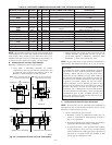
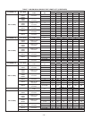
See Table 7 for maximum pipe lengths and Fig. 36, 37, 38, 39, and
40 for exterior piping arrangements.
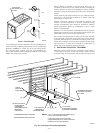
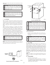
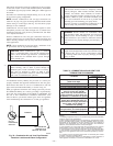
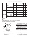
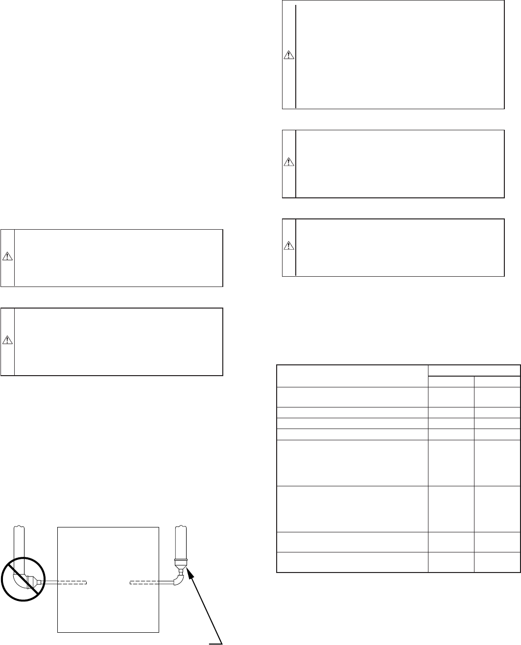
NOTE: Furnace combustion-air and vent pipe connections are
sized for 2-in. pipe. Any pipe size change should be made outside
furnace casing in vertical pipe. (See Fig. 32.) This allows proper
drainage of vent condensate.
Combustion-air and vent pipes must terminate together in same
atmospheric pressure zone, either through roof or sidewall (roof
termination preferred), using accessory termination kit. See Table
5 for required clearances.
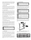
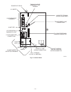
Furnace combustion-air and vent pipe connections must be at-
tached as shown in Fig. 27. Combustion-air intake plug fitting and
inducer housing alternate vent cap may need to be relocated in
some applications.
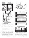
NOTE: Slope combustion-air and vent pipes a minimum of 1/4
in. per linear ft with no sags between hangers.
CAUTION: When combustion-air pipe is installed
above a suspended ceiling, pipe must be insulated with
3/8-in. thick Armaflex-type insulation. Combustion-air
pipe should also be insulated when it passes through
warm, humid space.
CAUTION: When vent pipe is exposed to temperatures
below freezing, such as when it passes through an
unheated space or when a chimney is used as a raceway,
pipe must be insulated as shown in Table 8 with
Armaflex-type insulation. Failure to follow this caution
will result in intermittent unit operation.
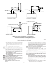
An abandoned masonry chimney may be used as a raceway for
properly insulated and supported combustion-air and vent pipes.
Each furnace must have its own set of combustion-air and vent
pipes and be terminated individually, as shown in Fig. 42.
Other gas appliances with their own venting system may also use
the abandoned chimney as a raceway providing it is permitted by
local code, the current edition of the NFGC or NSCNGPIC, and
the vent or liner manufacturer’s Installation Instructions. Care
must be taken to prevent the exhaust gases from one appliance
from contaminating the combustion air of other gas appliances.
CAUTION: Combustion air must not be taken from
inside structure because inside air is frequently contami-
nated by halogens, which include fluorides, chlorides,
bromides, and iodides. These elements are found in
aerosols, detergents, bleaches, cleaning solvents, salts, air
fresheners, adhesives, paint, and other household prod-
ucts. Locate combustion-air inlet as far as possible from
swimming pool and swimming pool pump house.
Excessive exposure to contaminated combustion air will
result in safety and performance related problems.
WARNING: Solvent cements are combustible. Keep
away from heat, sparks, and open flame. Use only in well
ventilated areas. Avoid breathing in vapor or allowing
contact with skin or eyes. Failure to follow this warning
could result in fire, property damage, personal injury, or
death.
WARNING: All combustion-air and vent pipes must be
airtight and watertight. Pipes must also terminate exactly
as shown in Fig. 36, 37, 38, 39, or 40. Failure to follow
this warning could result in property damage, personal
injury, or death.
Fig. 32—Combustion-Air and Vent Pipe Diameter
Transition Location and Elbow Configuration
A93034
FURNACE
PIPE DIAMETER
TRANSITION IN
VERTICAL SECTION
NOT IN
HORIZONTAL
SECTION
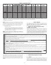
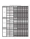
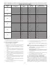
TABLE 5—COMBUSTION-AIR AND VENT PIPE
TERMINATION CLEARANCES
LOCATION
CLEARANCE (FT)
U.S.A. Canada
Above grade level or above antici-
pated snow depth
11†
Water heater/Dryer vent See Note 5 See Note 5
From plumbing vent stack 33
From any mechanical fresh air intake See Note 4 6
For furnaces with an input capacity
equal to or less than 100,000
Btuh—from any non-mechanical air
supply (windows or doors which can
be opened) or combustion-air opening
11
For furnaces with an input capacity
greater than 100,000 Btuh-from any
nonmechanical air supply (windows or
doors which can be opened) or
combustion-air opening
13
From service regulator vent, electric
and gas meters, and relief equipment
See Note 6 See Note 6
Above grade when adjacent to public
walkway
Note 3 Note 3
† 18 in. above roof surface in Canada.
NOTES:
1. If installing 2 adjacent Furnaces, refer to Multiventing and Vent Terminations
section for proper vent configurations.
2. When locating combustion-air and vent terminations, consideration must be
given to prevailing winds, location, and other conditions which may cause
recirculation of the appliance’s own flue products or the flue products of
adjacent vents. Recirculation can cause poor combustion, inlet condensate
problems, and accelerated corrosion of heat exchangers.
3. Vent termination can not terminate less than 2 ft horizontal and 7 ft above
public walkway or where condensate vapor or droplets may be a hazard.
4. Vent termination must be at least 3 feet above any forced draft inlets within
10 feet horizontal. Vent termination must be at least 3 feet horizontal from
other direct vent appliances intake unless otherwise specified by manufac-
turer.
5. 3 ft radius of furnace air-intake terminal and 1 ft horizontally from vertical
centerline of furnace air-intake terminal.
6. Above a meter/regulator within 3 feet horizontally of vertical centerline of
meter/regulator vent outlet to a maximum vertical distance of 15 feet.
—24—
→