


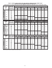
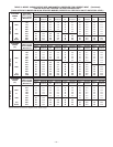
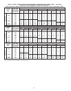
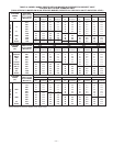
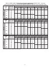

EXAMPLE: (0—2000 ft altitude using Table 9)
Heating value = 1050 Btu/cu ft
Specific gravity = 0.62
Therefore: Orifice No. 45
Manifold pressure 3.6-in. wc
* Furnace is shipped with No. 45 orifices. In this example
all main burner orifices are the correct size and do not need
to be changed to obtain the proper input rate.
Check and verify burner orifice size in furnace. NEVER ASSUME
ORIFICE SIZE; ALWAYS CHECK AND VERIFY.
2. Adjust manifold pressure to obtain input rate.
NOTE: Manifold pressure must always be measured with burner
enclosure front REMOVED. Gas meter must always be clocked
with burner enclosure front INSTALLED.
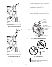
a. Remove burner enclosure front.
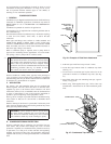
b. Remove cap that conceals adjustment screw for gas
valve regulator. (See Fig. 50.)
c. Jumper R and W thermostat connections on control to
start furnace operation.
d. Turn adjusting screw, counterclockwise (out) to decrease
manifold pressure or clockwise (in) to increase manifold
pressure.
NOTE: This furnace has been approved for a manifold pressure
of 3.2 in. wc to 3.8 in. wc when installed at altitudes up to 2000 ft.
For altitudes above 2000 ft, the manifold pressure can be adjusted
from 2.0 in. wc to 3.8 in. wc. If manifold pressure is outside this
range, change burner orifices to obtain pressure in this range.
CAUTION: DO NOT bottom out gas valve regulator
adjusting screw. This can result in unregulated manifold
pressure and result in excess overfire and heat exchanger
failures.
NOTE: If orifice hole appears damaged or it is suspected to have
been redrilled, check orifice hole with a numbered drill bit of
correct size. Never redrill an orifice. A burr-free and squarely
aligned orifice hole is essential for proper flame characteristics.
e. Replace gas valve regulator adjustment screw cap.
f. Replace burner enclosure front and verify adjusted gas
input rate using method outlined in item 3.
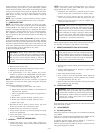
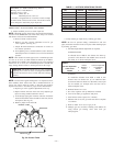
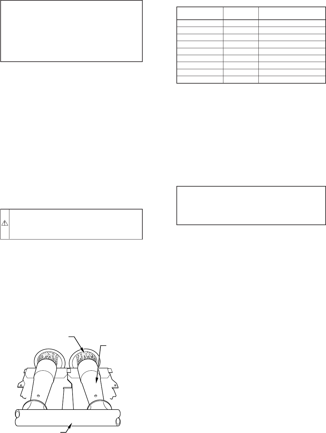
g. Look through sight glass in burner enclosure and check
burner flame. Burner flame should be clear blue, almost
transparent. (See Fig. 52.)
h. Remove jumper from R and W.
3. Verify natural gas input rate by clocking gas meter.
NOTE: Be sure all pressure tubing, combustion-air and vent
pipes, and burner enclosure front are in place when checking input
by clocking gas meter.
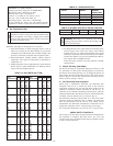
a. Calculate high-altitude adjustment (if required).
UNITED STATES
At altitudes above 2000 ft, this furnace has been ap-
proved for a 2% derate for each 1000 ft above sea level.
See Table 11 for derate multiplier factor.
EXAMPLE: 100,000 BTUH INPUT FURNACE INSTALLED AT
4300 FT.
Furnace Input Rate
at Sea Level
X
Derate
Multiplier
Factor
=
Furnace Input Rate
at Installation
Altitude
100,000 X 0.91 = 91,000
CANADA
At installation altitudes from 2000 to 4500 ft, this
furnace must be derated 5% by an authorized Gas
Conversion Station or Dealer. To determine correct input
rate for altitude, see example above and use 0.95 as
derate multiplier factor.
b. Reinstall burner box cover.
c. Gas valve regulator seal cap MUST be installed.
d. Turn off all other gas appliances and pilots.
e. Start furnace and let operate for 3 minutes.
f. Measure time (in sec) for gas meter test dial to complete
1 revolution.
g. Refer to Table 12 for cu ft of gas per hr.
h. Multiply gas rate (cu ft/hr) X heating value (Btu/cu ft)
using natural gas heating value from local gas
utility/supplier.
Fig. 52—Burner Flame
A89020
BURNER FLAME
BURNER
MANIFOLD
TABLE 11—ALTITUDE DERATE MULTIPLIER
ALTITUDE
(FT)
%OF
DERATE
DERATE MULTIPLIER
FACTOR FOR U.S.A.*
0—2000 0 1.00
2001—3000 4—6 0.95
3001—4000 6—8 0.93
4001—5000 8—10 0.91
5001—6000 10—12 0.89
6001—7000 12—14 0.87
7001—8000 14—16 0.85
8001—9000 16—18 0.83
9001—10,000 18—20 0.81
* Derate multiplier factor is based on midpoint altitude for altitude range.
—43—