


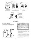
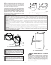
desired furnace side for field drain attachment. See Condensate
Trap Tubing (Factory-Shipped Orientation) section for drain tube
extension details. (See Fig. 5.)
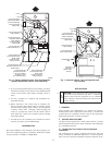
B. Condensate Trap Tubing (Factory-Shipped
Orientation)
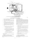
NOTE: See Fig. 6 or tube routing label on main furnace door to
confirm location of these tubes.
1. Collector Box Drain, Inducer Housing Drain, Relief Port,
and Pressure Switch Tubes
These tubes should be factory attached to condensate trap
and pressure switch ready for use in UPFLOW applications.
These tubes can be identified by their connection location
and also by a color label on each tube. These tubes are
identified as follows: collector box drain tube (blue label),
inducer housing drain tube (violet label or molded), relief
port tube (green label), and pressure switch tube (pink
label).
2. Condensate Trap Drain Tube
The condensate trap drain connection must be extended for
field attachment by doing the following:
a. Determine location of field drain connection. (See Fig. 2
or 6.)
NOTE: If internal filter is used, drain tube should be located to
opposite side of casing from return duct attachment to assist in
filter removal.
b. Remove and discard casing drain hole plug button from
desired side.
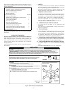
c. Install drain tube coupling grommet (factory-supplied in
loose parts bag) in selected casing hole.
d. Slide drain tube coupling (factory-supplied in loose parts
bag) through grommet ensuring long end of coupling
faces blower.
e. Cement 2 factory-supplied 1/2-in. street CPVC elbows to
the rigid drain tube connection on the condensate trap.
(See Fig. 6.) These elbows must be cemented together
and cemented to condensate trap drain connection.
NOTE: Failure to use CPVC elbows may allow drain to kink and
prevent draining.
f. Connect larger diameter drain tube and clamp (factory-
supplied in loose parts bag) to condensate trap and clamp
securely.
g. Route tube to coupling and cut to appropriate length.
h. Attach tube to coupling and clamp securely.
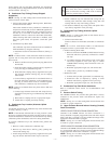
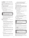
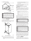
C. Condensate Trap Location (Alternate Upflow
Orientation)
An alternate location for the condensate trap is the left-hand side
of casing. (See Fig. 2 and 7.)
NOTE: If the alternate left-hand side of casing location is used,
the factory-connected drain and relief port tubes must be discon-
nected and modified for attachment. See Condensate Trap Tubing
(Alternate Upflow Orientation) section for tubing attachment.
To relocate condensate trap to the left-hand side, perform the
following:
1. Remove 3 tubes connected to condensate trap.
2. Remove trap from blower shelf by gently pushing tabs
inward and rotating trap.
3. Install casing hole filler cap (factory-supplied in loose parts
bag) into blower shelf hole where trap was removed.
WARNING: Casing hole filler cap must be installed in
blower shelf hole when condensate trap is relocated.
Failure to follow this warning could result in electrical
shock, fire, personal injury or death.
4. Install condensate trap into left-hand side casing hole by
inserting tube connection stubs through casing hole and
rotating until tabs snap into locking position.
5. Fill unused condensate trap casing holes with plastic filler
caps (factory-supplied in loose parts bag).
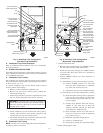
D. Condensate Trap Tubing (Alternate Upflow
Orientation)
NOTE: See Fig. 7 or tube routing label on main furnace door to
confirm location of these tubes.
1. Collector Box Drain Tube
Connect collector box drain tube (blue label) to condensate
trap.
NOTE: On 17-1/2-in. wide furnaces ONLY, cut tube between
corrugated sections to prevent kinks from occurring.
2. Inducer Housing Drain Tube
a. Remove and discard LOWER (molded) inducer housing
drain tube which was previously connected to conden-
sate trap.
b. Use inducer housing drain extension tube (violet label
and factory-supplied in loose parts bag) to connect
LOWER inducer housing drain connection to the con-
densate trap.
c. Determine appropriate length, cut, and connect tube.
d. Clamp tube to prevent any condensate leakage.
3. Relief Port Tube
a. Connect relief port tube (green label) to condensate trap.
b. Extend this tube (if required) by splicing to small
diameter tube (factory-supplied in loose parts bag).
c. Determine appropriate length, cut, and connect tube.
E. Condensate Trap Field Drain Attachment
Refer to Condensate Drain section for recommendations and
procedures.
F. Pressure Switch Tubing
The LOWER collector box pressure tube (pink label) is factory
connected to the pressure switch and should not require any
modification.
NOTE: See Fig. 6 or 7 or tube routing label on main furnace door
to check for proper connections.
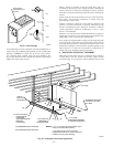
G. Upper Collector Box and Inducer Housing (Unused)
Drain Connections
UPPER COLLECTOR BOX DRAIN CONNECTION
Attached to the UPPER collector box drain connection is a
factory-installed corrugated, plugged tube (blue and white striped
label). This tube is plugged to prevent condensate leakage in this
application. Ensure this tube is plugged.
NOTE: See Fig. 6 or 7 or tube routing label on main furnace door
to check for proper connections.
UPPER INDUCER HOUSING DRAIN CONNECTION
Attached to the UPPER (unused) inducer housing drain connection
is a cap and clamp. This cap is used to prevent condensate leakage
in this application. Ensure this connection is capped.
NOTE: See Fig. 6 or 7 or tube routing label on main furnace door
to check for proper connections.
—7—