


48
d. Flame--Proving-- When the burner flame is proved at
the flame--proving sensor electrode FSE, the furnace
control CPU begins the blower--ON delay period and
continues to hold the gas valve GV open. If the burner
flame is not proved within two seconds, the control
CPU will close the gas valve GV, and the control CPU
will repeat the ignition sequence for up to three more
Trials--For--Ignition before going to Ignition--Lockout.
Lockout will be reset automatically after three hours
or by momentarily interrupting 115 vac power to the
furnace, or by interrupting 24 vac power at SEC1 or
SEC2 to the furnace control CPU (not at W, G, R, etc.)
If flame is proved when flame should not be present,
the furnace control CPU will lock out of Gas--Heating
mode and operate the inducer motor IDM until flame
is no longer proved.
e. Blower--On Delay-- If the burner flame is proven, the
blower motor is energized on HEAT speed 25 sec after
the gas valve GV is energized.
Simultaneously, the electronic air cleaner terminal
EAC--1 is energized and remains energized as long as
the blower motor BLWM is energized.
f. Blower--Off Delay-- When the thermostat is satisfied,
the R--to--W circuit is opened, de--energizing the gas
valve GV, stopping gas flow to the burners, and de--
energizing the humidifier terminal HUM. The inducer
motor IDM will remain energized for a 5--second
post--purge period. The blower motor BLWM and air
cleaner terminal EAC--1 will remain energized for 90,
120, 150, or 180 seconds (depending on the blower--
OFF delay selection). The furnace control CPU is fact-
ory--set for a 120--second blower--OFF delay.
2. Cooling Mode
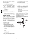
(See Fig. 26 for thermostat connections.) The thermostat
closes the R--to--G--and--Y circuits. The R--to--Y circuit
starts the outdoor unit, and the R--to--G and Y circuits start
the furnace blower motor BLWM on COOL speed. The
electronic air cleaner terminal EAC--1 is energized with
115 vac when the blower motor BLWM is operating.
When the thermostat is satisfied, the R--to--G--and--Y cir-
cuits are opened. The outdoor unit will stop, and the fur-
nace blower motor BLWM will continue operating on the
COOL speed for an additional 90 sec. Cut jumper J2 to
reduce the cooling off--delay to 5 sec. (See Fig. 25.)
3. Continuous Blower Mode
When the R--to--G circuit is closed by the thermostat, the
blower motor BLWM will operate on continuous--blower
speed (same as HEAT speed). Terminal EAC--1 is ener-
gized as long as the blower motor BLWM is energized.
During a call for heat, the blower BLWM will stop during
igniter warm--up (17 sec), ignition, and blower--ON delay
(25 sec), allowing the furnace heat exchangers to heat up
more quickly, then restarts at the end of the blower--ON
delay period at HEAT speed.
When the thermostat “calls for cooling”, the blower motor
BLWM will operate at COOL speed. When the thermostat
is satisfied, the blower motor BLWM will operate an addi-
tional 90 sec, on COOL speed before reverting back to
continuous blower speed.
When the R--to--G circuit is opened, the blower motor
BLWM will continue operating for an additional 5 sec, if
no other function requires blower motor BLWM opera-
tion.
4. Heat Pump
When installed with a heat pump, the furnace control auto-
matically changes the timing sequence to avoid long
blower off times during demand defrost cycles. When the
R--to--Wand-- Y or R--to--W--and--Y--and--G circuits are
energized the furnace control CPU will continue to turn on
the blower motor BLWM at HEAT speed, and begin a
heating cycle. The blower motor BLWM will remain on
until the end of the prepurge period, then shut off for 24
sec then come back on at HEAT speed. When the W input
signal disappears, the furnace control begins a normal in-
ducer post--purge period and the blower switches to
COOL speed after a 3 sec delay. If the R--to--W--and--
Y--and--G signals disappear at the same time, the blower
motor BLWM will remain on for the selected blower--
OFF delay period. If the R--to--W--and--Y signals disap-
pear, leaving the G signal, the blower motor BLWM will
continue running the blower motor at HEAT speed after
the selected blower--OFF delay period is completed.
Step 4 —Wiring Diagrams
Refer to Fig. 25 and 41 for wiring diagrams.
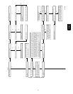
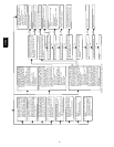
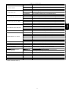
Step 5 —Troubleshooting
Refer to the service label. (See Fig. 45–Service Label.)
The Troubleshooting Guide can be a useful tool in isolating
furnace operation problems. Beginning with the word Start,
answer each question and follow the appropriate arrow to the next
item.
The Guide will help to identify the problem or failed component.
After replacing any component, verify correct operation
sequence.
310AAV