


32
START--UP, ADJUSTMENT, AND SAFETY
CHECK
Step 1 —General
FIRE HAZARD
Failure to follow this warning could result in personal
injury, death and/or property damage.
This furnace is equipped with manual reset limit switches in
the gas control area. The switches open and shut off power
to the gas valve if a flame rollout or overheating condition
occurs in the gas control area. DO NOT bypass the
switches. Correct inadequate combustion air supply
problem before resetting the switches.
!
WARNING
CUT HAZARD
Failure to follow this caution may result in personal injury.
Sheet metal parts may have sharp edges or burrs.
Use care and wear appropriate protective clothing, safety
glasses, and gloves when handling parts and servicing
furnaces.
CAUTION
!
1. Maintain 115--v wiring and ground. Improper polarity will
result in rapid flashing LED and no furnace operation.
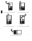
2. Make thermostat wire connections at the 24--v terminal
block on the furnace control. Failure to make proper con-
nections will result in improper operation. (See Fig. 26.)
3. Gas supply pressure to the furnace must be greater than
4.5--In. W.C. (0.16 psig ) but not exceed 14--In. W.C. (0.5
psig).
4. Check all manual--reset switches for continuity.
5. Install blower compartment door. Door must be in place to
operate furnace.
6. Replace outer door.
Step 2 —Start--Up Procedures
FIRE AND EXPLOSION HAZARD
Failure to follow this warning could result in personal
injury, death and or property damage.
Never test for gas leaks with an open flame. Use a
commercially available soap solution made specifically for
the detection of leaks to check all connections.
!
WARNING
1. Purge gas lines after all connections have been made.
2. Check gas lines for leaks.
ELECTRICAL SHOCK HAZARD
Failure to follow this warning could result in personal
injury, or death.
Blower access door switch opens 115--v power to control.
No component operation can occur unless switch is closed.
Caution must be taken when manually closing this switch
for service purposes.
!
WARNING
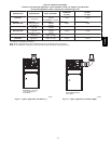
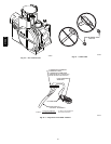
3. To Begin Component Self--Test: Remove blower access
door. Disconnect the thermostat R lead from the furnace
control board. Manually close the blower door switch.
Short (jumper) the COM--24v terminal on control to the
TEST/TWIN 3/16--inch quick connect terminal on control
until LED goes out (approximately 2 sec). Gas valve and
humidifier will not be turned on. (See Fig. 25.)
NOTE: The furnace control allows all components, except the
gas valve, to be run for short period of time. This feature helps
diagnose a system problem in case of a component failure.
Component test feature will not operate if any thermostat signal is
present at the control.
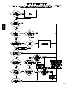
Component test sequence is as follows:
Refer to service label attached to furnace or see Fig. 45.
a. LED will display previous status code 4 times.
b. Inducer motor starts and continues to run until Step f
of component test sequence.
c. Hot surface igniter is energized for 15 sec., then off.
d. Blower motor operates on HEAT speed for 10 sec.
e. Blower motor operates on COOL speed for 10 sec.
f. Inducer motor stops.
g. Reconnect R lead to furnace control board, release
blower door switch and re--install blower door.
4. Operate furnace per instruction on door.
5. Verify furnace shut down by lowering thermostat setting
below room temperature.
6. Verify furnace restarts by raising thermostat setting above
room temperature.
Step 3 —Adjustments
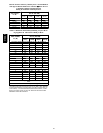
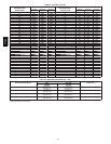
Table 11—Altitude Derate Multiplier for U.S.A.
ALTITUDE
FT. (M)
PERCENT
OF DERATE
DERATE MUL TIPLIER
FACTOR*
0–2000
(0---610)
0 1.00
2001–3000
(610---914)
8–12 0.90
3001–4000
(914---1219)
12–16 0.86
4001–5000
(1219---1524)
16–20 0.82
5001–6000
1524---1829)
20–24 0.78
6001–7000
(1829---2134)
24–28 0.74
7001–8000
(2134---2438)
28–32 0.70
8001–9000
(2438---2743)
32–36 0.66
9001–10,000
(2743---3048)
36–40 0.62
* Derate multiplier factors are based on midpoint al titude for altitude
range.
FIRE HAZARD
Failure to follow this warning could result in injury, death
and/or property damage.
DO NOT bottom out gas valve regulator adjusting screw.
This can result in unregulated manifold pressure and result
in excess overfire and heat exchanger failures.
!
WARNING
310AAV