


20
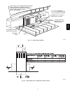
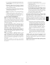
2” (51mm)
Street Elbow
A08551
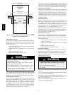
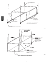
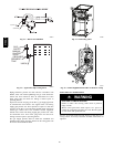
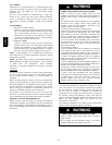
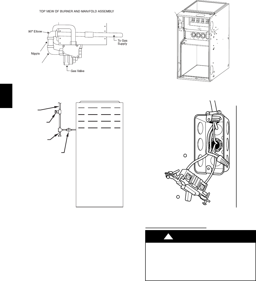
Fig. 21 --- Burner and Manifold
UNION
SEDIMENT
TRAP
MANUAL
SHUTOFF
VALVE
(REQUIRED)
GAS
SUPPLY
A02035
Fig. 22 --- Typical Gas Pipe Arrangement
Piping should be pressure and leak tested in accordance with
NFGC, local, and national plumbing and gas codes before the
furnace has been connected. After all connections have been
made, purge lines and check for leakage at furnace prior to
operating furnace.
If pressure exceeds 0.5 psig (14--In. W.C.), gas supply pipe must
be disconnected from furnace and capped before and during
supply pipe pressure test. If test pressure is equal to or less than
0.5 psig (14--In. W.C.), turn off electric shutoff switch located on
furnace gas control valve and accessible manual equipment
shutoff valve before and during supply pipe pressure test. After
all connections have been made, purge lines and check for
leakage at furnace prior to operating furnace.
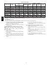
The gas supply pressure shall be within the maximum and
minimum inlet supply pressures marked on the rating plate with
the furnace burners ON and OFF.
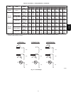
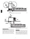
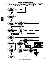
Factory
Factory
Installed
Installed
Alternate
Alternate
Location
Location
A10291
Fig. 23 --- Relocating J--Box
A10141
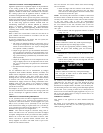
Fig. 24 --- Field--Supplied Electrical Box on Furnace Casing
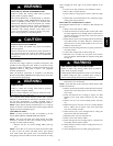
ELECTRICAL
CONNECTIONS
ELECTRICAL SHOCK HAZARD
Failure to follow this warning could result in personal
injury or death.
Blower access panel door switch opens 115--v power to
control. No component operation can occur. Do not bypass
or close switch with panel removed.
!
WARNING
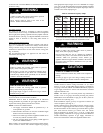
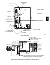
See Fig. 26 for field wiring diagram showing typical field 115--v
wiring. Check all factory and field electrical connections for
tightness.
310AAV