


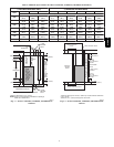
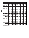
3
A
A
B
[736.9]
[736.9]
29
29
Ø7/8
Ø7/8
[22.2]
[22.2]
ACCESSORY
ACCESSORY
5 15/16
5 15/16
[150.7]
[150.7]
28.39
28.39
[721.2]
[721.2]
Ø7/8
Ø7/8
[22.2]
[22.2]
ACCESSORY
ACCESSORY
14 7/8
14 7/8
[337.3]
[337.3]
(BOTH SIDES)
(BOTH SIDES)
Ø7/8
Ø7/8
[22.2]
[22.2]
ACCESSORY
ACCESSORY
Ø7/8
Ø7/8
[22.2]
[22.2]
ACCESSORY
ACCESSORY
Ø1 3/4
Ø1 3/4
[44.5]
[44.5]
GAS ENTRY
GAS ENTRY
Ø1/2
Ø1/2
[12.7]
[12.7]
THERMOSTAT WIRE ENTRY
THERMOSTAT WIRE ENTRY
22 1/16
22 1/16
[560]
[560]
SIDE INLET
SIDE INLET
(BOTH SIDES)
(BOTH SIDES)
11 7/16
11 7/16
[290.7]
[290.7]
9 11/16
9 11/16
[245.4]
[245.4]
[197.8]
[197.8]
7 13/16
7 13/16
Ø7/8
Ø7/8
[22.2]
[22.2]
J.BOX PROVISION
J.BOX PROVISION
Ø7/8
Ø7/8
[22.2]
[22.2]
JUNCTION BOX
JUNCTION BOX
LOCATION
LOCATION
Ø1 3/4
Ø1 3/4
[44.5]
[44.5]
GAS ENTRY
GAS ENTRY
1 15/16
1 15/16
[49.2]
[49.2]
1
[25.4]
[25.4]
1 1/4
1 1/4
[31.8]
[31.8]
29 9/16
29 9/16
[750.7]
[750.7]
1 15/16
1 15/16
[49.2]
[49.2]
5 5/8
5 5/8
[143.3]
[143.3]
5 7/16
5 7/16
[138.5]
[138.5]
6 13/16
6 13/16
[172.3]
[172.3]
Ø1/2
Ø1/2
[12.7]
[12.7]
THERMOSTAT WIRE ENTRY
THERMOSTAT WIRE ENTRY
19
19
[481.7]
[481.7]
OUTLET
OUTLET
D
21.6
21.6
[549.5]
[549.5]
BOTTOM INLET
BOTTOM INLET
C
33 1/4
33 1/4
[843.9]
[843.9]
9 9/16
9 9/16
[243.3]
[243.3]
3/4
3/4
[19.1]
[19.1]
5 7/8
5 7/8
[148.5]
[148.5]
3 7/16
3 7/16
[86.8]
[86.8]
9 7/8
9 7/8
[250.7]
[250.7]
27 3/4
27 3/4
[704.7]
[704.7]
2 5/16
2 5/16
[59]
[59]
FRONT OF CASING
FRONT OF CASING
TOP OF CASING
TOP OF CASING
4 13/16
4 13/16
[122.2]
[122.2]
27 3/4
27 3/4
[704.7]
[704.7]
5 7/8
5 7/8
[148.5]
[148.5]
8 5/8
8 5/8
[219]
[219]
5 1/2
5 1/2
[140.3]
[140.3]
8 7/16
8 7/16
[213.5]
[213.5]
FRONT OF CASING
FRONT OF CASING
TOP OF CASING
TOP OF CASING
6.1
6.1
[155.7]
[155.7]
2 1/16
2 1/16
[51.6]
[51.6]
5.1
5.1
[130.5]
[130.5]
1.7
1.7
[43.5]
[43.5]
Ø7/8
Ø7/8
[22.2]
[22.2]
ACCESSORY (2)
ACCESSORY (2)
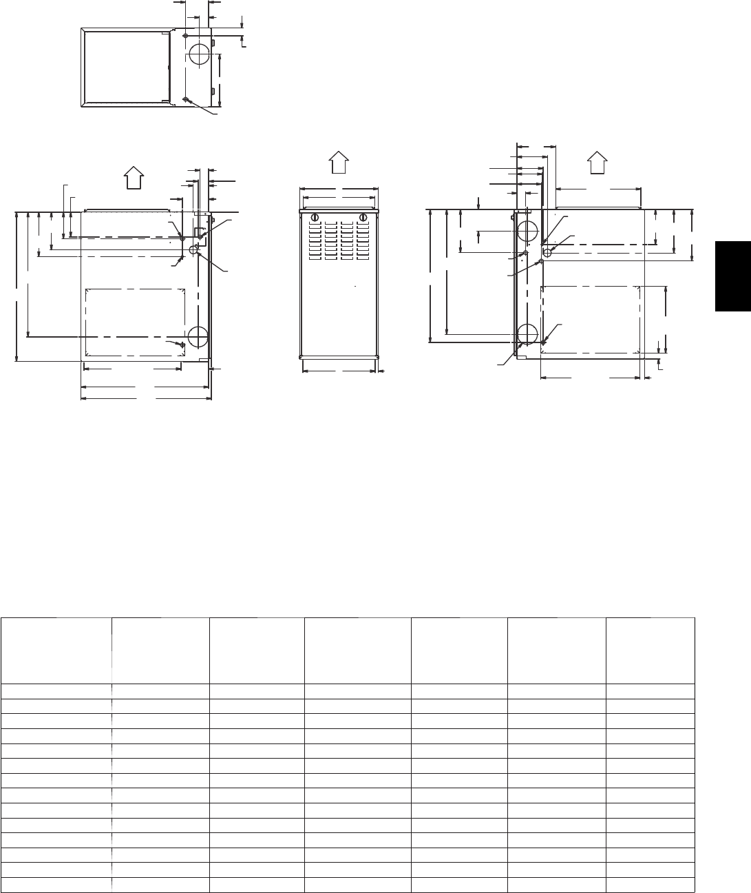
AIR FLOW
AIR FLOW
AIR FLOW
AIR FLOW
BOTTOM RETURN
BOTTOM RETURN
WIDTH
WIDTH
AIR FLOW
AIR FLOW
KNOCK OUTS FOR
KNOCK OUTS FOR
VENTING(5
VENTING(5
PLACES)
PLACES)
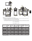
A10290
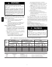
NOTES:
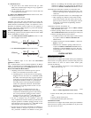
1. Two a ddi tional 7/8---in. (22 mm) diameter holes are located in the top plate.
2. Minimum return---air openings at furnace, based on metal duct. If flex duct is used, see flex duct manufacturer’s recommendations for equivalent diameters.
(a.) For 800 CFM---16---in. (406 mm) round or 14 1/2 x 12---in. (368 x 305 mm) rectangle.
(b.)For 1200 CFM---20---in. (508 mm) roun d or 14 1/2 x 19 1/2---in. (368 x 495 mm) r ectangle.
(c.)For 1600 CFM---22---in. (559 mm) roun d or 14 1/2 x 22 1/16---in. (368 x 560mm) rectangle.
(d.)For airflow requirements above 1800 CFM, see Air Delivery table in Product Data literature for specific use of single side inlets. The use of both side
inlets, a combination of 1 side and th e bottom, or the bottom only will ensure adequate return air openings f or airflow requirements above 1800 CFM.
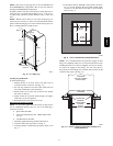
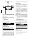
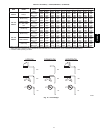
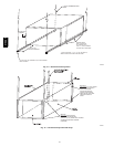
Fig. 1 --- Dimensional Drawing
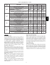
Table 1—Dimensions -- In. (mm)
FURNACE SIZE
A
CABINET
WIDTH
B
OUTLET
WIDTH
C
TOP & BOTTOM
FLUE COLLAR
LOCATION
D
BOTTOM
INLET WIDTH
VENT
CONNECTION
SIZE
SHIP WT
LB (KG)
045---08/024045 14---3/16 (360) 12---9/16 (319) 9---5/16 (237) 12---11/16 (322) 4 (102) 104 (47)
045---12/036045 14---3/16 (360) 12---9/16 (319) 9---5/16 (237) 12---11/16 (322) 4 (102) 107 (49)
070---08/024070 14---3/16 (360) 12---9/16 (319) 9---5/16 (237) 12---11/16 (322) 4 (102) 111 (50)
070---12/036070 14---3/16 (360) 12---9/16 (319) 9---5/16 (237) 12---11/16 (322) 4 (102) 115 (52)
070---16/048070 17---1/2 (445) 15---7/8 (403) 11---9/16 (294) 16 (406) 4 (102) 126 (57)
090---14/042090 17---1/2 (445) 15---7/8 (403) 11---9/16 (294) 16 (406) 4 (102) 127 (58)
090---16/048090 21 (533) 19---3/8 (492) 13---5/16 (338) 19---1/2 (495) 4 (102) 140 (64)
090---20/060090 21 (533) 19---3/8 (492) 13---5/16 (338) 19---1/2 (495) 4 (102) 146 (66)
110---12/036110 17---1/2 (445) 15---7/8 (403) 11---9/16 (294) 16 (406) 4 (102) 135 (61)
110---16/048110 21 (533) 19---3/8 (492) 13---5/16 (338) 19---1/2 (495) 4 (102) 146 (66)
110---22/066110 21 (533) 19---3/8 (492) 13---5/16 (338) 19---1/2 (495) 4 (102) 152 (69)
135---16/048135 21 (533) 19---3/8 (492) 13---5/16 (338) 19---1/2 (495) 4 ( 102)* 149 (68)
135---22/066135 24---1/2 (622) 22---7/8 (581) 15---1/16 (383) 23 (584) 4 (102)* 163 (74)
155---20/060155 24---1/2 (622) 22---7/8 (581) 15---1/16 (383) 23 (584) 4 (102)* 170 (77)
*135 and 155 size furnaces r e quire a 5 or 6---in. (127 or 152 mm) vent. Use a vent adapter between furna ce and vent stack. See Installation Instructions for
complete installation requirements.
310AAV