


43
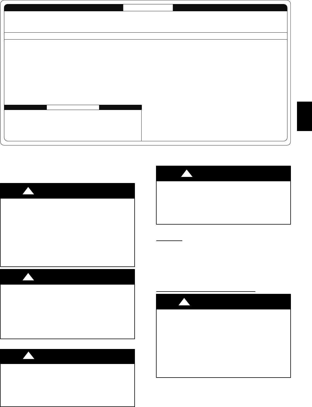
To initiate the component test sequence, shut OFF the room thermostat or disconnect the "R"
thermostat lead. Briefly short the TEST/TWIN terminal to the "Com 24V" terminal. Status LED
will flash code and then turn ON the inducer motor. The inducer motor will run for the entire
component test. The hot surface ignitor, blower motor fan speed (on AMBER LED boards
only) blower motor-heat speed, and blower motor-cool speed will be turned ON for 10-15
seconds each. Gas Valve and Humidifier will not be turned on.
CONTINUOUS OFF - Check for 115VAC at L1 and L2, and 24VAC at SEC-1 and SEC-2.
CONTINUOUS ON - Control has 24VAC power.
RAPID FLASHING - Line voltage (115VAC) polarity reversed. If twinned, refer to twinning kit instructions.
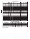
LED CODE
STATUS
11 NO PREVIOUS CODE - Stored status code is erased automatically after 72 hours. On
RED LED boards stored status codes can also be erased when power
(115 VAC or 24 VAC) to control is interrupted.
12 BLOWER ON AFTER POWER UP (115 VAC or 24 VAC) -Blower runs for 90 seconds,
if unit is powered up during a call for heat (R-W closed) or R-W opens during blower
on-delay.
13 LIMIT CIRCUIT LOCKOUT - Lockout occurs if the limit, draft safeguard, flame rollout, or
blocked vent switch (if used) is open longer than 3 minutes.
- Control will auto reset after three hours. - Refer to #33.
14 IGNITION LOCKOUT - Control will auto-reset after three hours. Refer to #34.
21 GAS HEATING LOCKOUT - Control will NOT auto reset.
Check for: - Mis-wired gas valve -Defective control (valve relay)
22 ABNORMAL FLAME-PROVING SIGNAL - Flame is proved while gas valve is de-
energized. Inducer will run until fault is cleared. Check for: - Leaky gas valve
- Stuck-open gas valve
23 PRESSURE SWITCH DID NOT OPEN Check for:
- Obstructed pressure tubing. - Pressure switch stuck closed.
24 SECONDARY VOLTAGE FUSE IS OPEN Check for:
- Short circuit in secondary voltage (24VAC) wiring.
If status code recall is needed, briefly remove then reconnect one main limit wire to display stored status code. On RED LED boards do not remove power or blower door before initiating status code recall. After
status code recall is completed component test will occur.
327596-101 REV. B
31 PRESSURE SWITCH DID NOT CLOSE OR REOPENED - If open longer than five minutes,
inducer shuts off for 15 minutes before retry. Check for: - Excessive wind
- Proper vent sizing - Defective inducer motor
- Low inducer voltage (115VAC) - Defective pressure switch
- Inadequate combustion air supply - Disconnected or obstructed pressure tubing
- Low inlet gas pressure (if LGPS used) - Restricted vent
If it opens during blower on-delay period, blower will come on for the selected blower
off-delay.
33 LIMIT CIRCUIT FAULT - Indicates a limit, draft safeguard, flame rollout, or blocked vent
switch (if used) is open. Blower will run for 4 minutes or until open switch remakes
whichever is longer. If open longer than 3 minutes, code changes to lockout #13.
If open less than 3 minutes status code #33 continues to flash until blower shuts off.
Flame rollout switch and BVSS require manual reset. Check for: - Restricted vent
- Proper vent sizing - Loose blower wheel. - Excessive wind
- Dirty filter or restricted duct system.
- Defective blower motor or capacitor. - Defective switch or connections.
- Inadequate combustion air supply (Flame Roll-out Switch open).
34 IGNITION PROVING FAILURE - Control will try three more times before lockout #14
occurs. If flame signal lost during blower on-delay period, blower will come on for the
selected blower off-delay. Check for: - Flame sensor must not be grounded
- Oxide buildup on flame sensor (clean with fine steel wool).
- Proper flame sense microamps (.5 microamps D.C. min., 4.0 - 6.0 nominal).
- Gas valve defective or gas valve turned off - Manual valve shut-off
- Defective Hot Surface Ignitor - Control ground continuity
- Low inlet gas pressure - Inadequate flame carryover or rough ignition
- Green/Yellow wire MUST be connected to furnace sheet metal
45 CONTROL CIRCUITRY LOCKOUT Auto-reset after one hour lockout due to;
- Gas valve relay stuck open - Flame sense circuit failure - Software check error
Reset power to clear lockout. Replace control if status code repeats.
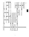
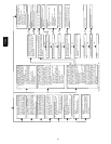
SERVICE
COMPONENT TEST
EACH OF THE FOLLOWING STATUS CODES IS A TWO DIGIT NUMBER WITH THE FIRST DIGIT DETERMINED BY THE NUMBER OF SHORT FLASHES AND THE SECOND DIGIT BY THE NUMBER OF LONG FLASHES.
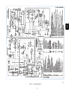
A04223
Fig. 45 --- Service Label
SERVICE AND MAINTENANCE
PROCEDURES
FIRE, EXPLOSION, ELECTRICAL SHOCK
HAZARD
Failure to follow this warning could result in personal
injury, death and/or property damage.
The ability to properly perform maintenance on this
equipment requires certain knowledge, mechanical
skills, tools, and equipment. If you do not possess these,
do not attempt to perform any maintenance on this
equipment other than those procedures recommended in
the User’s Manual.
!
WARNING
ELECTRICAL SHOCK, FIRE OR EXPLOSION
HAZARD
Failure to follow this warning could result in personal
injury or death, or property damage.
Before servicing, disconnect all electrical power and install
lockout tag to furnace. Verify proper operation after
servicing.
!
WARNING
ELECTRICAL OPERATION HAZARD
Failure to follow this caution may result in improper
furnace operation.
Label all wires prior to disconnection when servicing
controls. Wiring errors can cause improper and dangerous
operation.
CAUTION
!
ENVIRONMENTAL HAZARD
Failure to follow this caution may result in environmental
pollution.
Remove and recycle all components or materials (i.e. oil,
refrigerant, et.) before unit final disposal.
CAUTION
!
Step 1 —Introduction
GENERAL
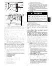
These instructions are written as if the furnace is installed in an
upflow application. An upflow furnace application is where the
blower is located below the combustion and controls section of
the furnace, and conditioned air is discharged upward. Since this
furnace can be installed in any of the 4 positions shown in Fig. 4,
you must revise your orientation to component location
accordingly.
ELECTRICAL CONTROLS AND
WIRING
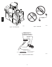
ELECTRICAL SHOCK HAZARD
Failure to follow this warning could result in personal
injury or death.
Before installing, modifying, or servicing system, main
electrical disconnect switch must be in the OFF position and
install a lockout tag. There may be more than one electrical
supply to the furnace. Check accessories and cooling unit
for additional electrical supplies that must be shut off during
furnace servicing. Lockout and tag switch with a suitable
warning label. Verify proper operation after servicing.
!
WARNING
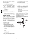
The electrical ground and polarity for 115--v wiring must be
properly maintained. Refer to Fig. 26 for field wiring information
and to Fig. 41 for furnace wiring information.
NOTE: If the polarity is not correct, the STATUS LED on the
control will flash rapidly and prevent the furnace from heating.
310AAV