


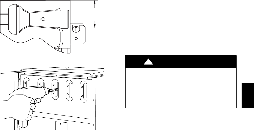
47
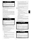
1-7/8
(47.6 mm)
A05026
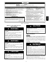
Fig. 47 --- Igniter Position--Top View
A01050
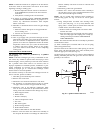
Fig. 48 --- Cleaning Heat Exchanger Cell
(4) Insert brush end of cable in burner inlet opening of cell, and
proceed to clean 2 lower passes of cell in same manner as upper
pass.
(5) Repeat foregoing procedures until each cell in furnace has
been cleaned.
(6) Using vacuum cleaner, remove residue from each cell.
(7) Using vacuum cleaner with soft brush attachment, clean
burner assembly.
(8) Clean flame sensor with fine steel wool.
(9) Install NOx baffles (if removed).
(10) Reinstall burner assembly. Center burners in cell openings.
10. Remove old sealant from cell panel and collector box
flange.
11. Spray releasing agent on the heat exchanger cell panel
where collector box assembly contacts cell panel.
NOTE: A releasing agent such as cooking spray or equivalent
(must not contain corn or canola oil, aromatic or halogenated
hydrocarbons or inadequate seal may occur) and RTV sealant
(G.E. 162, 6702, or Dow--Corning 738) are needed before
starting installation. DO NOT substitute any other type of RTV
sealant. G.E. 162 (P771--9003) is available through RCD in 3--oz
tubes.
12. Apply new sealant to flange of collector box and attach to
cell panel using existing screws, making sure all screws
are secure.
13. Reconnect wires to the following components. (Use con-
nection diagram on wiring label, if wires were not marked
for reconnection locations.):
a. Draft safeguard switch.
b. Inducer motor.
c. Pressure switch(es).
d. Limit over--temperature switch.
e. Gas valve.
f. Hot surface igniter.
g. Flame--sensing electrode.
h. Flame rollout switches.
i. Install NOx baffles (if removed).
14. Reinstall internal vent pipe, if applicable.
15. Reinstall vent connector on furnace vent elbow. Securely
fasten vent connector to vent elbow with 2 field--supplied,
corrosion--resistant, sheet metal screws located 180_ apart.
16. Replace blower access door only, if it was removed.
17. Set thermostat above room temperature and check furnace
for proper operation.
18. Verify blower airflow and speed changes between heating
and cooling.
FIRE OR EXPLOSION HAZARD
Failure to follow this warning could result in personal
injury, death and/or property damage.
Never test for gas leaks with an open flame. Use a
commercially available soap solution made specifically for
the detection of leaks to check all connections.
!
WARNING
19. Check for gas leaks.
20. Replace outer access door.
Step 3 —Sequence of Operation
NOTE: Furnace control must be grounded for proper operation
or control will lock out. Control is grounded through
green/yellow wire routed to gas valve and manifold bracket
screw.
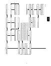
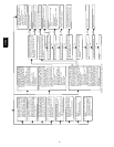
Using the schematic diagram in Fig. 41, follow the sequence of
operation through the different modes. Read and follow the
wiring diagram very carefully.
NOTE: If a power interruption occurs during a call for heat (W),
the control will start a 90--sec blower--only ON period two
seconds after power is restored, if the thermostat is still calling for
gas heating. The amber LED light will flash code 12 during the
90--sec period, after which the LED will be ON continuous, as
long as no faults are detected. After the 90--sec period, the furnace
will respond to the thermostat normally.
The blower door must be installed for power to be conducted
through the blower door interlock switch ILK to the furnace
control CPU, transformer TRAN, inducer motor IDM, blower
motor BLWM, hot--surface igniter HSI, and gas valve GV.
1. Heating
(See Fig. 26 for thermostat connections.) The wall thermo-
stat “calls for heat,” closing the R--to--W circuit. The fur-
nace control performs a self--check, verifies the pressure
switch contacts PRS are open, and starts the inducer motor
IDM.
a. Inducer Prepurge Period-- As the inducer motor
IDM comes up to speed, the pressure switch contacts
PRS close, 24 VAC power is supplied for a field in-
stalled humidifier at the HUM terminal and the control
begins a 15--sec prepurge period.
b. Igniter Warm--Up-- At the end of the prepurge period,
the Hot--Surface igniter HSI is energized for a
17--second igniter warm--up period.
c. Trial--for--Ignition Sequence-- When the igniter
warm--up period is completed, the main gas valve re-
lay contacts GVR close to energize the gas valve GV,
the gas valve opens, The gas valve GV permits gas
flow to the burners where it is ignited by the HSI. Five
seconds after the GVR closes, a 2--second flame prov-
ing period begins. The HSI igniter will remain ener-
gized until the flame is sensed or until the 2--second
flame proving period begins.
310AAV